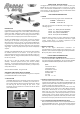
POWER SYSTEM - GLOW OR ELECTRIC? The biggest decision you will have to make is whether to power your RASCAL 80 with a glow engine (2-stroke or 4-stroke) or an electric motor. We have flown the RASCAL 80 on a variety of both types of power systems, and we make the following recommendations based on our successful on-field experience. GLOW POWER RECOMMENDATIONS ❑ ENGINE We recommend the following engine sizes for the RASCAL 80. 2-STROKE - .46 to.55 cu. in. 4-STROKE - .53 to .65 cu. in. SIG carries O.S.
volts) provides flight performance similar to a .55 glow engine. We in front of each part description. Please also note that the bolts and find that 5000mAh LiPo packs provide between 10 to 15 minutes of nuts required to mount your engine to the motor mounts are not flight time, depending on propeller selection and other factors included and must be purchased separately. (quality of pack, throttle management, outside temperature, etc.).
Fuel Tank for Glow Engine ❑ (1) Fuel Tank Body - 295cc (10 oz.) ❑ (1) Rubber Stopper ❑ (1) M3 x 34mm Bolt ❑ (1) Metal Clunk Pick-Up ❑ (3) Plastic Tube - 4mm od x 60mm ❑ (2) Zip-Ties ❑ (1) 5/16" x 3/4" x 3-3/16" Balsa Fuel Tank Retainer should be set to about 220OF - 250OF (104OC - 121OC) as measured on the bottom of the iron using a thermometer.
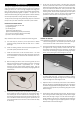
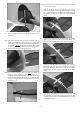
f) WING ASSEMBLY The wings are designed as a 2-piece system, with separate right and left wing panels joined by an aluminum tube wing joiner and a hardwood locating pin at the rear. Due to the high strength of the wing joiner tube, the wing panels do not need to be permanently glued together. Gluing them permanently together is optional – it’s your call. The obvious benefit to leaving the wing panels separate is the fact that they can be easily transported or stored, requiring a minimum of space.
e) Turn the part over and glue the other side of the hinge. Continue this process until you have glued both sides of all the hinges! Keep a rag handy to wipe off any excess thin CA glue. (If you get some glue smears on the plastic covering, don't worry about them right now. Once all the hinging is done, you can clean the smears off the covering with CA De-bonder. f) Let the glue dry 10-15 minutes before flexing the hinges. At first you might notice a little stiffness in the joint.
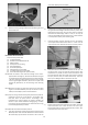
FUSELAGE ASSEMBLY INSTALL THE MAIN LANDING GEAR Locate the following parts from the kit contents: (1) Fuselage (1) Aluminum Main Landing Gear (3) M4 x 20 mm Socket-Head Bolts (3) M4 Split-Ring Lock Washers (2) 3" dia. Main Wheels (2) 4 mm dia.
(1) (2) (1) (2) (2) (3) (1) (6) (6) c) Tailwheel Assembly Coiled Steering Springs Steering Arm M3 x 12 mm Screws Split Lock Washers Nylon Control Horns Nylon Control Horn Retaining Plates M2 x 14 mm Screws M2 Nuts Use a fine line felt tip pen to mark some guide lines on the stabilizer that will make it easy for you to realign the stab after the glue is applied in the next step. You can now remove the pins and take the stabilizer off the fuselage for gluing.
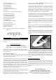
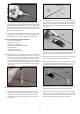
❑ 19) Next we will mount the Tailwheel Assembly in place on the lower rear end of the fuselage. b) a) Begin by placing the three armed rudder steering horn on the bottom of the rudder. The front edge of the steering horn should be 1 / 4” back from the beveled edge of the rudder. Mark the location of the two steering arm holes on the bottom edge of the rudder.
metal clevis halfway onto the threads. e) Attach the steering springs to the three armed steering horn and the tailwheel horn.
f) g) a) Locate the pull-pull hardware bag, and lay out the parts. b) Thread an M3 nut and a metal clevis onto the brass rigging coupler. Do this step four times. Make sure that the elevator servo is in neutral position and then adjust the metal clevis at the tail end as needed to get the c) elevator in perfect neutral position.
e) When the loops are pulled tight, crimp the middle 1/3 of the ELECTRIC POWER SYSTEM tube to lock the wire in place. At this point, connect metal clevis to the middle hole on one of the rudder control horns, and slide Skip this section if you’re using a glow engine power setup the pull-pull wire into the guide tube in the fuselage.
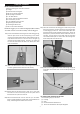
e) Tack glue the firewall in place. Recheck once more to make sure that the front of the firewall is at the correct distance from the back of the motor mount box. That distance plus the length of your motor must equal 5-3/8”. When satisfied it is correct, glue the firewall securely to the rest of the motor mount box. ❑ 28) Bolt the plywood motor mount box to the Fuselage with M4 x 20 mm Socket-Head Bolts and M4 Flat Metal Washers.
c) c) Now route the ESC’s servo wire into the fuselage, and temporarily connect it to the receiver. Cut the hook strap in half, and then glue one end of it to the other box side. The hook side should be glued against the wood. Epoxy glue works best for this step. d) Connect the ESC's motor wires to the motor. Operate the motor d) and check the direction of rotation. NEVER DO THIS WITH A PROPELLER INSTALLED! If you need to reverse the rotation, refer to the instructions that came with the motor and ESC.
f) c) Slide the cowl back into position with the four pieces of tag board on the outside of the cowl. Carefully reposition the cowl and tape it in place with low-tack masking tape. Now drill the four cowl mounting holes through the cowl. g) d) Remove the tape, cowl, and tag board from the fuselage. Screw each of the four cowl screws into a hole and then remove the screws. e) Add a drop of thin CA to each of the four cowl mounting screw holes to harden the holes.
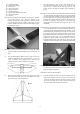
engine may require some alterations and/or specialized fittings (not Option #1) Cut one or more cooling slots in the bottom of the cowl as supplied). shown. A Dremel® Tool, or similar rotary hand-tool, with an assortment of bits is without a doubt the best tool to use For this section you will need the Fuselage and: for making cutout in the fiberglass cowling.
stopper and seal the stopper in the tank. Do not over tighten ❑ 37) Set your engine in place on the beams of the engine mounts. the screw as it can cause the tank to split. Attach three 6Slide the engine forward or aft on the engine mounts until the inch lengths of silicone fuel tubing (not furnished) to the tank front of the engine's thrust washer is 5-3/8" from the front of and label them appropriately as FILL, CARB, and VENT so you the firewall.
you do not need access to that area. We recommend simply tack gluing the hatch in place with a couple small tabs of glue. Then seal over the seams with either clear tape or white covering material (not supplied). ❑ 43) 2-STROKE THROTTLE PUSHROD a) The first step is to install your throttle servo in the fuselage using the rubber grommets, eyelets, and screws that came with the servo. Mount the throttle servo in the front opening of the servo tray, with the servo control arm to the front.
Note: A Dremel® Tool, or similar powered hand-tool, with an assortment of sanding bits is without a doubt the best tool to use for making holes in the fiberglass cowling. However, if you do not have access to such a power tool, you can cut the opening with a drill, a hobby knife, and a file - by first drilling a series of almost touching holes inside the pattern lines (1/8” dia.
INSTALL SIDE WINDOWS ❑ 48) From the kit contents, locate the bag containing the molded clear plastic side windows. The clear windows are molded to fit into the fuselage window frames from the inside. Note that each window has a flange all the way around the outside perimeter to provide an easy gluing surface. You may need to trim the flanges a little closer than the factory did, in order to fit them in place. A sharp scissors or snips works best for trimming the windows.
RECOMMENDED BALANCE RANGE: 3-1/2” to 3-3/4” Behind the Leading Edge of the Wing (Anywhere within this range is acceptable.) Always make it part of your pre-flight routine to check each control on the airplane, making sure the surfaces are moving in the correct directions. Also check each control linkage to be sure they are secure and that nothing is loose.
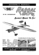
flight performance, and safety of the finished model. SIG MFG. CO.’s obligation shall be to replace those parts of the kit proven to be SIG MFG. CO., INC. is committed to your success in both assembling defective or missing. The user shall determine the suitability of the and flying the RASCAL 80 EG ARF. Should you encounter any problem product for his or her intended use and shall assume all risk and liability building this kit or discover any missing or damaged parts, please feel in connection therewith.
REMOVING THE HATCH FROM THE RASCAL 80 The Top Hatch is held on the fuselage by 2 pins at the front (under the rear edge of the cowling), and 2 magnets at the back of the hatch. To remove the top hatch from the fuselage grasp the hatch near the top of the windshield and lift straight up to disengage the rear magnets. When that happens and the bottom rear corner of the hatch clears the front fuselage former, the hatch will lift back and off easily. SIG MFG CO., INC. 401 S. Front St. Montezuma, Iowa 50171 U.