SIGELNT User Manual SPD1000X Programmable Linear DC Power Supply UM0501X-E02A 2018 SIGLENT TECHNOLOGIES CO.
SIGLENT Copyright and Declaration Copyright SIGLENT TECHNOLOGIES CO.,LTD. All Right Reserved. Trademark Information SIGLENT is a registered trademark of SIGLENT TECHNOLOGIES. Declaration SIGLENT products are protected by patent law in and outside of the People’s Republic of China .
SIGELNT General Safety Summary Please review the following safety precautions carefully to avoid personal injury or damage to this product or any product connected to it. To prevent potential danger, please use the instrument as specified. Use the proper power cord Only the power cord designed for the instrument and authorized by the local country should be used. Power supply AC Input Voltages: 100/120/220/230 V ± 10%,50/60 Hz Use the proper fuse The fuse type: 100/120 V: T6.3A/250V 220/230 V : T3.
SIGELNT To avoid fire or electric shock, please examine all ratings and symbols on the instrument. Read this guide carefully to learn more details about the ratings before connection. Keep proper ventilation Inadequate ventilation may cause an increase of temperature within the instrument, which can lead to instrument damage. Please maintain proper ventilation and check the fan and air-vents regularly when using the instrument.
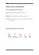
SIGELNT Safety Terms and Symbols Terms may appear on the product: DANGER: Indicates direct injury or hazard that may occur. WARNING: Indicates potential injury or hazard that may occur. CAUTION: Indicates potential damage to the instrument or other property that may occur.
SIGELNT SPD1000X Brief Introduction The Siglent SPD1000X Programmable DC Power Supply has a 2.8 inch TFT-LCD screen, programmable output, and real time graphical trending display. The SPD1168X has maximum output values of 16 V/8 A. The SPD1305X has maximum output values of 30 V/5 A. Both models provide remote sensing as well as output short circuit and overload protection. The SPD1000X is suitable for a variety of applications in research and development, production and repair.
SIGELNT Stable, reliable and low noise: ≤ 350 uVrms/3 mVpp Fast Transient Response Time: < 50 μs Maximum resolution of 1 mV, 1 mA with 5-digit voltage and 4-digit current display. Timer function sequences preset output values High resolution 2.
SIGELNT Content Copyright and Declaration ......................................................................................... I General Safety Summary.......................................................................................... II Safety Terms and Symbols ......................................................................................IV SPD1000X Brief Introduction ................................................................................... V Chapter 1 Start Guide ...........
SIGELNT Chapter 1 Start Guide In this chapter, we introduce the front panel and display interface of the SPD1000X, and also tips for how to check and operate the power supply the first time.
SIGELNT 1.1 General Inspection Please check the instrument according to the following steps: 1. Inspect the shipping container Keep the shipping container and cushioning material until the contents of the shipment have been completely checked and the instrument has passed both electrical and mechanical tests. The consigner or carrier is responsible for damages to the instrument resulting from shipment. SIGLENT will not provide free maintenance or replacement for shipping damages. 2.
SIGELNT 1.
SIGELNT 1. LCD Display 2.8 inch TFT-LCD is used to display system parameter settings, system output state, menu options, prompt messages, etc. 2. Knob When setting parameters, rotate the knob to increase or decrease the value of the digit at the cursor. In the Store Page the knob can be used to quickly move to the desired file. 3. Function button and power key When setting parameters, press the Fine button to move the cursor to select the position of digit to be modified.
SIGELNT Press the Timer / Wave button for approximately 1 second or longer period to enter the waveform display mode. Press the button briefly to configure the network connection information. Then press the left / right buttons to step through the different IP Page addresses and fields. Choose the DHCP field, then press the On/Off button to turn off the IP Setting menu. Press the IP/Save button for 1 second or longer to enter the storage function system.
SIGELNT 7. Power key Turns the instrument on or off. 1.
SIGELNT 1. Warning message Warning message regarding proper grounding and instrument maintenance. 2. AC input voltage description The frequency, voltage and the specified fuse should correspond to the AC input mains. 3. AC power socket The socket for AC input power. 4. Fuse The specified fuse must be rated for the input voltage (Please refer to the “ AC input voltage description “) 5. AC line power selection switch AC Input Voltages: 100/120/220/230 V 6.
SIGELNT 1.4 Connect Power The power supply supports a variety of AC line power input values. For each line voltage, the rear panel voltage selector settings are different, as shown in table 1 below. Table 1: AC input line power specifications AC power input Voltage selector configure 100 VAC ± 10%, 50 ~ 60 Hz 120 VAC ± 10%, 50 ~ 60 Hz 220 VAC ± 10%, 50 ~ 60 Hz 230 VAC ± 10%, 50 ~ 60 Hz Please connect the external AC power carefully using the steps below: 1.
SIGELNT 3. Check the fuse When the instrument leaves the factory, the specified fuse is installed. Please check whether the fuse matches the actual input voltage according to the "Input Power Requirements" on the rear panel of the instrument. 4. Connect the power Connect the instrument to AC power supply using the power cord provided with the accessories. Then press the button to turn on the power.
SIGELNT 1.5 User Interface 1. Channel output state On / Off 2. Remote sense mode 2 wire:two wire mode,4 wire:four wire(remote sense)mode. 3. LAN connection icon When the instrument is connected to a network through the LAN port this flag is displayed. 4.
SIGELNT DEVEICE interface this icon is displayed. 5. Output mode CV:Constant Voltage,CC:Constant Current. 6. Output programmed values Voltage,current,power settings 7. Measured output values Voltage,current,power actual output 8.
SIGELNT 1.6 Output Inspection 1. Check the output voltage (1) Turn on the power and make certain the channel current setting is not zero when the instrument has no-load. (2) Press on/off button, the supply should be working in constant voltage (CV) mode. You can check the voltage range of SPD1168X by adjusting the voltage setpoint from the minimum (0 V) to the maximum value (16 V) and the voltage range of SPD1305X by adjusting the voltage setpoint from the minimum (0 V) to the maximum value (30 V). 2.
SIGELNT 1.7 Fuse Replacement The specifications of the fuse are relative to the actual input line voltage, shown in the table below. You also can refer to the rear panel “input power requirement”. Input voltage 100/120 VAC 220/230 VAC Fuse specification T6.3A T3.15A To replace the fuse,please follow the steps below: 1. Turn off the instrument and remove the power cord. 2. Insert a small straight screwdriver into the slot at the power socket and gently pry out the fuse seat. 3.
SIGELNT Chapter 2 Control panel operation In this chapter, the functions and operation of the SPD1000X control panel will be introduced in detail.
SIGELNT 2.1 Output summary The SPD1000X provides a floating output. The output rating of the SPD1168X is 0-16 V / 0-8 A,while the output rating of SPD1305X is 0-30 V / 0-5 A; Two modes of output: constant voltage (CV) and constant current (CC); Two types of operation: two wire mode and remote sense mode. Constant voltage output/constant current output: In the constant current mode, the output current is a set value which can be controlled by the front panel.
SIGELNT 16 SPD1000X User Manual
SIGELNT 2.2 2-wire mode The operation of the output power configuration follows: Operation method: 1) Connect the output terminals As shown in the figure below, connect the load to the output terminals. CAUTION To avoid damages to the instrument, please pay attention to the positive and negative terminal polarities when connecting.
SIGELNT a) Selecting the parameters to change by moving the left / right arrow keys. b) Press Fine button to select the data’s position, then rotate the knob to change the parameter. 3) Enable the output Make certain the mode is 2-wire (the Vsense key is off and the display shows 2-wire). Press the On/Off button, the button light will light up, the channel output is enabled and the display shows the power supply status is "On".
SIGELNT 2.3 Remote Sense mode When the power supply is outputting a large current, a voltage drop can occur as a result of resistance in the output cable. To ensure an accurate output voltage, the SPD1000X provides a 4-wire (remote sense) mode of operation. In this mode, the voltage at the load terminal is detected instead of the voltage at the power supply output.
SIGELNT cursor b) Press Fine button to select the cursor’s position, then rotate the knob to adjust the parameter. 3、 Open the 4-wire mode Press Vsense button, the button will light up. The power supply screen will show ‘4 wire’ on the display. 4、 Enable the output Press the on/off button, the button light is lit and the power supply display shows “on”. Note: In 4-wire mode, the maximum compensation voltage of the power supply is 1 V.
SIGELNT 2.4 Configuration of LAN interface The SPD1000X supports USB Device and LAN interfaces. You can remotely control the SPD1000X through these interfaces. When using the LAN interface, first set the interface parameters. Operation methods: 1. Use the network cable to connect the LAN port on the rear panel with the network where the computer or computers are located; 2. Press IP/Save briefly to enter the network setting interface. 3.
SIGELNT pressed or the Fine button is pressed for 1 second or longer.) 4. Press IP/Save again to exit the network setting interface and return to the main screen.
SIGELNT 2.5 Save and recall The SPD1000X allows the user to save the current instrument status (including operating modes, voltage/current settings, timer parameters, etc.) to the internal memory and recall saved files when required. Save Operation steps: 1. Set the parameter settings to be saved; 2. Press IP/Save for 1 second or longer to enter to the Store Page screen. 3. Press the direction button to move the cursor to “FILE CHOICE”; 4.
SIGELNT Recall Operation steps: 1. Pres IP/Save button for 1 second or longer to enter to the Store Page screen. 2. Press the left and right arrow buttons to move the cursor to "FILE CHOICE". 3. Turn the rotary knob or press the Fine button briefly to select the instrument status file (FILE 1 ~ FILE 5). 4. Press the arrow buttons to move the cursor to "OPER CHOICE" 5.
SIGELNT Delete 1. Press IP/Save for 1 second or longer to enter the Store Page interface; 2. Press the left and right arrow buttons to move the cursor to "FILE CHOICE". 3. Turn the rotary knob or press the Fine button briefly to select the instrument status file (FILE 1 ~ FILE 5). 4. Press the arrow button to move the cursor to "OPER CHOICE" 5. Turn the multi-function knob to select "DELETE" and press the knob or press the Fine button for 1 second or longer to select "OK" to read the saved file.
SIGELNT 26 SPD1000X User Manual
SIGELNT 2.6 Timer The SPD1000X provides a timer function. The timer can save five sets of settings, each set independent of the others. The user can set arbitrary parameters within the voltage, current, and dwell time values. The timer supports continuous output, with the longest time-out time of up to 10000 s. Set the timer parameter Method 1: 1. Press Timer/Wave to enter the Timer Setup interface, and the indicator will illuminate. 2.
SIGELNT Start the Timer 1. Using the arrow keys, move cursor to Timer at the bottom of the screen in the Timer interface screen. 2. Rotate the multi-function knob to turn the Timer state to “ON”; 3. Press the knob to start the Timer. Notice the countdown shown to the right of the Timer On/ Off indicator. It will begin to count down for each segment of the timer profile.. 4. Rotate the multi-function knob to turn the Timer state to “OFF” 5.
SIGELNT Method 2: 1. Press Timer/Wave button to enter the Timer interface. 2. Press the knob, start the timer profile. 3. Press the knob again, turn off the timer. 4. Or press the On/Off button for 1 second or longer to turn on/off the Timer.
SIGELNT After starting the timer function, the timer will stop if you press the On/Off button to switch off the channel output. When the channel output is turned on again, the timer will continue counting from the last point in time it stopped. After the countdown steps have completed the timer will turn off automatically.
SIGELNT 2.7 Waveform display The SPD1000X displays the dynamic changing of the voltage and the current in the form of a trending graph. Operation steps: 1. Press the Timer/Wave key for 1 second or longer to open the channel waveform display function. Once activated, the key light will illuminate and the waveform display interface is activated. 2. Press the On/Off key to turn on the output. Now you can observe the near-real-time changes of the channel output parameters (current/voltage).
SIGELNT 2.8 Version information Under any interface, press Ver/Lock to enter the version information display interface. Version information includes: the number of instrument power-up boot cycles, software version, hardware version, product model, product serial number.
SIGELNT 2.9 Lock key The SPD1000X allows the user to lock the front panel keys to avoid the risk of inadvertently changing a setting. Under any interface on the front panel, press the Ver/Lock key for 1 second or longer to enable the key lock function. At this point, the other buttons on the front panel are disabled, except for the power button. After the lock function is enabled, a "lock" icon appears at the top of the screen. Press and hold the Ver/Lock key again to disable the key lock function.
SIGELNT 2.10 Upgrade firmware Software Upgrades are performed using Easypower, a PC-based management software program (available on the Siglent website), this is used to update the power supplies firmware via USB Device or LAN. Upgrade as follows: 一、 Upgrade in normal Interface 1. Open the EasyPower software after the USB interface has established its connection to the PC run the EasyPower software. 2. Click Version and then choose Upgrade in the drop-down menu to enter the USB firmware upgrade dialogue.
SIGELNT 3. Figure shows the firmware upgrade dialogue. Click file choosing icon , and then select the file to be upgraded which must have an ADS extension. 4. As is shown in figure 4, click Upgrade button to begin the upgrade. The upgrade is finished when the progress bar completes and the instrument will automatically run the version after the upgrade.
SIGELNT 二、 Upgrade Via Guide Procedure Upgrade via guide procedure also can be used if the method above does not work. Specific steps are as follows: 1. Press the knob and simultaneously turn on the instrument. It will now enter the guide procedure mode. 2. After entering the guide procedure mode, the upgrade method is the same as in the previous procedure.
SIGELNT Chapter 3 Remote control 3.1 Control method Based on NI-VISA Users can remotely control the instrument by using NI-VISA from NI (National Instruments Corporation). In regards to NI-VISA, there is a full version and a live version (Run-Time Engine version). The full version includes NI device drivers and a tool called NI MAX. NI MAX is a user interface that controls the device. The real-time version is much smaller than the full version and includes only NI device drivers.
SIGELNT basic communication technology in computer networks. It allows applications to communicate through network hardware and the standard network protocol built into the operating system. This method requires two-way communication between the instrument and the computer network through an IP address and a fixed port number. SPD1000X Socket communication port is 5025.
SIGELNT Brackets ({}) contain parameter choices. Brackets are not sent with the command string. Vertical line (|) separates parameter selections. Angle brackets (<>) indicates that you must specify a value for the parameter inside the brackets. For example, for the parameter in angle brackets for the above command, you must specify a value for this parameter (for example, "CH1: VOLT 10"). Angle brackets do not send angle brackets along with the command string.
SIGELNT 10、 [SOURce:]CURRent ? 11、 [SOURce:]VOLTage 12、 [SOURce:] VOLTage? 13、 OUTPut 14、 OUTPut:TRACk 15、 OUTPut:WAVE 16、 TIMEr:SET 17、 TIMEr:SET? 18、 TIMEr 19、 SYSTem:ERRor? 20、 SYSTem:VERSion? 21、 SYSTem: STATus? 40 SPD1000X User Manual
SIGELNT 3.4 Command description 1、 *IDN? Command format *IDN? Description Query the manufacturer, product type, series NO. , software version and hardware version. Return Info Manufacturer, product type, series NO., software version. Example Siglent, SPD1168X, SPD1XDAD1R0001, 2.01.01.06,V1.0 2、 *SAV Command format *SAV Description Save current state in nonvolatile memory with the specified name.
SIGELNT Description Select the channel that will be operated. Example INSTrument CH1 Command format INSTrument? Description Query the current operating channel Example INSTrument? Return Info CH1 5、 MEASure Command format MEASure: CURRent? < CH1|CH2> Description Query current value for specified channel, if there is no specified channel, query the current channel. Example MEASure: CURRent? CH1 Return Info 3.
SIGELNT 6、 CURRent Command format CURRent :={CH1} Description Set current value of the selected channel Example CH1:CURRent 0.5 Command format : CURRent? :={CH1} Description Query the current value of the selected channel. Example CH1: CURRent? Return Info 0.
SIGELNT 8、 MODE Command MODE:SET {2W|4W} Description To set the work operation of 2W or 4W Example MODE:SET 4W 9、 OUTPut Command format OUTPut , :={CH1}; :={ON|OFF} Description Turn on/off the channel. Example OUTPut CH1, ON 10、 TIMEr Command format TIMEr: SET , , , ,
SIGELNT Return Info 3, 0.5, 2 Command format TIMEr , :={CH1}; < state >;={ON | OFF}; Description Turn on/off Timer function of specified channel Instruction The command works effectively only when starts from 1. Example 11、 TIMEr CH1, ON SYSTem Command format SYSTem: ERRor? Description Query the error code and the information of the equipment. Command format SYSTem: VERSion? Description Query the software version of the equipment.
SIGELNT as follows. Example SYSTem: STATus? Return info 0x0224 Explanation: The returned information is hexadecimal, so the user needs to convert to binary format when confirming the status. See the following table: Bit NO.
SIGELNT Return Info 10.11.13.214 13、 MASKaddr Command format MASKaddr Description Used to assign a subnet mask to the instrument Example MASKaddr 255.255.255.0 Explanation This command is invalid when the power is currently set to automatically obtain the network configuration (DHCP is ON) Command format MASKaddr? Description Query the software the setting of mask address Example SYSTem: VERSion? Return Info 255.255.255.
SIGELNT Command format MASKaddr? Description Query the software the setting of gateway address Return Info 10.11.13.1 15、 DHCP Command format DHCP{ON|OFF} Description Turn on or off the instrument's automatic network configuration feature.
SIGELNT 3.5 Programming examples This section lists examples of programming with SCPI commands based on NI-VISA or Socket in Visual C ++, Visual Basic, MATLAB, Python, and more. NI-VISA-based programming examples 1. First confirm that your computer has installed the NI VISA library (NI website can be downloaded from http://www.ni.com). The default installation path in this article is C: \Program Files\IVI Foundation\VISA. 2.
SIGELNT USBTMC and TCP/IP, send commands to read the return value. Follow these steps to complete the example: 1、 Open Visual Studio and create a new vc ++ win32 project. Setting up the project environment to use the ni-visa library, you have two options for using ni-visa, static mode and automatic mode: (1) static mode: Find the files on the NI-VISA installation path: visa.h, visatype.h, visa32.lib. Copy them to your project and add them to the project. In the project .
SIGELNT \MSC. Set this path to Project - Performance - Connector - General additional library directory, as shown: Set the library file:project---properties---Linker---Command Line---Additional Options:visa32.lib Including visa.h file: in XXX.cpp file: #include 2、 Add code (1) Based on USB interface code : Write a Usbtmc_test function.
SIGELNT connected to the system and tries to read back the result using a read-write function */ /* The general flow of the code is to open the Explorer */ /* Open the VISA session to the instrument */ /* Use viPrintf to write the instrument flag */ /* Try to read a response with viScanf */ /* Close the VISA session */ /***********************************************************/ ViSession defaultRM; ViSession instr; ViUInt32 numInstrs; ViFindList findList; ViStatus status; char instrReso
SIGELNT /** Look for all USB TMC VISA resources in our system */ /* Then the number of resources stored in the system numInstrs Lane*/ status = viFindRsrc (defaultRM, "USB?*INSTR", &findList, &numInstrs, instrResourceString); if (status < VI_SUCCESS) { printf ("An error occurred while finding resources.\nHit enter to continue."); fflush(stdin); getchar(); viClose (defaultRM); return status; } We will now open a VISA session for all USB TMC instruments.
SIGELNT char * cmmand ="*IDN?\n"; status = viPrintf (instr, cmmand); if (status < VI_SUCCESS) { printf ("Error writing to the device %d.\n", i+1); status = viClose (instr); continue; } /** Now we will try to read back the response of a device information query from the device. We will use the viScanf function to get the data. After the data is read out, the response is displayed */ status = viScanf(instr, "%t", buffer); if (status < VI_SUCCESS) printf ("Error reading a response from the device %d.\n", i+1)
SIGELNT status = viOpen (defaultRM, head, VI_LOAD_CONFIG, VI_NULL, &instr); if (status < VI_SUCCESS) { printf ("An error occurred opening the session\n"); viClose(defaultRM); } status = viPrintf(instr, "*idn?\n"); status = viScanf(instr, "%t", outputBuffer); if (status < VI_SUCCESS) { printf("viRead failed with error code: %x \n",status); viClose(defaultRM); }else printf ("\ndata read from device: %*s\n", 0,outputBuffer); status = viClose (instr); status = viClose (defaultRM); return 0; } SPD1000X User Man
SIGELNT Visual Basic programming examples Environment: Windows 7 32-bit systerm , Microsoft Visual Basic 6.0 Example Content: Using NI-VISA, access control devices via USBTMC and TCP/IP, send commands to read the return value. Follow the steps to complete the example: 1 Open Visual Basic, create a standard application project (Standard EXE). 2 Using the NI-VISA library to set up the project environment, click on the project's existing tab >> add module.
SIGELNT (USBTMC) instrument. Create a VISA-USB object to connect to the USB instrument vu = visa ('ni', 'USB0 :: 0xF4EC :: 0x1300 :: 0123456789 :: INSTR'); fopen(vu); fprintf(vu,'*IDN?'); outputbuffer = fscanf(vu); disp(outputbuffer); fclose(vu); delete(vu); clear vu; end (2) Based on the LAN port code: Write to the TCP_IP_Test function. function TCP_IP_test( IPstr ) % This code demonstrates using NI-VISA to send synchronous read and write commands to a TCP / IP instrument.
SIGELNT fprintf(vt,'*IDN?'); % Request data outputbuffer = fscanf(vt); disp(outputbuffer); %Close the VISA object fclose(vt); delete(vt); clear vt; end 58 SPD1000X User Manual
SIGELNT Socket-based programming examples Python programming examples Because the operating system itself supports Socket communication, this communication method is relatively concise. Note that the SPD1000X uses a fixed port number of 5025 for Socket communication, and the "\ n" (newline) must be added to the end of the SCPI command string. Environment: Windows 7 32-bit system, Python v2.7.5 Example content: Access control devices via Socket, send commands to read the return value.
SIGELNT Sock.sendall(cmd) time.sleep(1) except socket.error: print ('Send failed') sys.exit() reply = Sock.recv(4096) return reply def SocketClose(Sock): Sock.close() time.sleep(.300) def main(): global remote_ip global port global count s = SocketConnect() for i in range(10): qStr = SocketQuery(s, b'*IDN?\n') print (str(count) + ":: " + str(qStr)) count = count + 1 SocketClose(s) input('Press "Enter" to exit') if __name__ == '__main__': proc = main() 60 SPD1000X User Manual
SIGELNT Chapter 4 Common troubleshooting The most commonly encountered failures and their solutions are listed below. Please use these steps listed if an error occurs. If the problem persists, please contact SIGLENT . 1. The instrument will not power on. (1) Check whether the power is correctly connected. (2) Check whether the power switch at the front panel is on.
SIGELNT 3. The constant current output is abnormal. (1) Check whether the maximum output power of the scale currently selected fulfills the load requirement. If yes, go to the next step. (2) Check whether the cable connecting the load and power supply is short-circuited and is making good contact. (3) Check whether the load is normal. (4) Check whether the voltage setting value of this scale is proper; if it is too low, increase it properly. (5) If the problem persists, please contact SIGLENT.
SIGELNT Chapter 5 Service and Support 5.1 Maintenance summary SIGLENT warrants that the products that it manufactures and sells will be free from defects in materials and workmanship for a period of three years from the date of shipment from an authorized SIGLENT distributor. If a product or CRT proves defective within the respective period, SIGLENT will provide repair or replacement as described in the complete warranty statement.