
User's Manual


SIGMA DESIGNS Windeo Reference Design Module User Guide
Page 3/9
1. Introduction
This user’s guide provides information for operating the Windeo Reference Design Module. This
Reference board is the RF/Baseband UWB Transceiver using Sigma Windeo Chipset. The Windeo chip set
is based on the Wimedia Aliance Multi-band OFDM (MBOA) PHY v1.1 and MAC v1.0 Specifications and
is comprised of two devices:
• Windeo RF IC (B7CW101)
• Windeo Baseband IC (B7CW201)
The Reference Board supports PCI/SPI interface and is capable of transmit multiple HD video streams
over-the-air to multiple HDTVs simultaneously.
1.1 Sigma Chip set
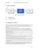
1.1.1 Windeo Baseband IC (B7CW201)
The B7CW201 is divided into three main blocks.
1. Medium Access Control (MAC)
2. Physical Layer (PHY)
3. RF Macro (ADC, DAC and PLL)
The B7CW201 requires 33-MHz system clock supplied by an external oscillator from RF section. PLL use
this 33Mhz clock to generate 528Mhz clock require for ADC and DAC. Clock divider circuit generate all
required clocks for PHY and MAC.
1.1.2 Windeo RF IC (B7CW101)
• A RF transmitter and receiver for Ultra Wideband (UWB) frequencies
• Based on the WiMedia Alliance Multi-Band Orthogonal Frequency Division Modulation
(MBOFDM) communications Specifications for frequencies between 3168MHz
to 4752MHz
• Supports data rates up to 480Mbps
• Uses multiple receivers to permit non line-of-site reception with the Windeo® Baseband
B7CW201 processor device
• Supports the 3 MBOA Group 1 bands, centered at 3.43GHz, 3.96GHz and 4.48GHz,
with a bandwidth of 528MHz each.
• Supports Band hopping and the ability to select or change the channel
• Supports TFI and FFI modes
• Supports power save mode
• Only a single external resistor and RF baluns required
1.2 Main external components.
Main external components include:
• Flash
• SDRAM
• Regulators
• RF baluns
• RF BPFs
• T/R switch.