SERVICE MANUAL (INTERNATIONAL) IMPINGER CONVEYOR OVENS MODEL 1433-000-E, 1434-000-E, 1456, 1457 WITH PUSH BUTTON CONTROLS Lincoln Foodservice Products, LLC 1111 North Hadley Road Fort Wayne, Indiana 46804 United States of America Phone : (800) 374-3004 U.S. Fax: (888) 790-8193 • Int’l Fax: (260) 436-0735 Technical Service Hot Line (800) 678-9511 www.lincolnfp.
SEQUENCE OF OPERATION IMPINGER ADVANTAGE SERIAL NUMBER N28654 AND ABOVE (OVENS WITH PUSH BUTTON CONTROLS) MODEL 1433-000-E MODEL 1434-000-E MODEL 1456 MODEL 1457 POWER SUPPLY CONTROL BOX AUTO COOL DOWN MAIN FAN CIRCUIT BURNER CIRCUIT TEMPERATURE CONTROL CONVEYOR DRIVE 2 230VAC 230VAC 220/240VAC 220/240VAC 50 HZ. 50 HZ. 50 HZ. 50 HZ. NAT. GAS LP GAS NAT. GAS LP GAS Electrical power is to be supplied to the oven by a three conductor service. Brown conductor is hot. Blue conductor is neutral.
SCHEMATIC DIAGRAM MODEL 1433-000-E, 1434-000-E SERIAL NUMBER N28654 TO N31348 Impinger I – Adv Digital – Gas Service Manual – International 3
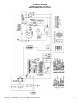
SCHEMATIC DIAGRAM MODEL 1456, 1457 SERIAL NUMBER N28654 TO N31348 4 Impinger I – Adv Digital – Gas Service Manual – International
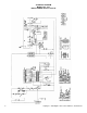
SCHEMATIC DIAGRAM MODEL 1433-000-E, 1434-000-E, 1456, 1457 SERIAL NUMBER N31349 AND ABOVE Impinger I – Adv Digital – Gas Service Manual – International 5
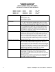
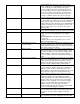
TROUBLESHOOTING GUIDE IMPINGER ADVANTAGE GAS OVENS SERIAL NUMBER N28654 AND ABOVE (OVENS WITH PUSH BUTTON CONTROLS) SYMPTOM Oven fan will not run POSSIBLE CAUSE Incoming power supply Fuse, 10 Amp Fuse holder Switch, oven power Motor, main fan No control box cooling Incoming power supply Fuse, 10 Amp Fuse holder Switch, oven power Cooling fan No automatic control box cooling Incoming power supply Cooling fan thermostat Control box cooling fan continues to run Cooling fan thermostat Oven will not he
Ignition control Burner reset switch Burner blower motor Burner blower motor air pressure switch Spark generator Igniter/sensor assembly Gas valve Flame will not stay on Flame sensor Power supply Ignition control Impinger I – Adv Digital – Gas Service Manual – International WITH POWER OFF: Remove 3 prong plug (on gas valve) and measure continuity between terminals 2 and 3. If no continuity, check the following: Proper gas pressure supply to gas valve as marked on the oven specification plate.
Oven will not heat S/N N31349 and Above Main fan Gas supply Air pressure switch Oven cavity hi-limit thermostat Ignition control Burner reset switch Burner blower motor Burner blower motor air pressure switch Ignition control Igniter/sensor assembly Ignition control Gas valve 8 not stay on, check the reset button for the ignition control. If the above check okay, replace ignition control.
Pilot tube Pilot orifice Flame will not stay on Flame sensor Power supply Ignition control Low flame is on, but no main flame NOTE: Flame should be on at this time Control transformer Oven control Thermocouple Impinger I – Adv Digital – Gas Service Manual – International there is voltage to the pilot valve, but there is no gas pressure, replace gas valve. Check for gas pressure at pilot tube. Disconnect pilot tube at burner and connect manometer.
Oven control Thermocouple Oven control Temperature regulation valve Intermittent heating Thermal/overload of main fan and burner blower motor Conveyor will not run Incoming power supply Fuse, 10 Amp Fuse holder Switch, oven power Control transformer Conveyor motor Capacitor, conveyor motor Switch, conveyor reversing Oven control Conveyor motor runs, but there is no speed display 10 NOTE: Display will indicate “BELT JAM” Oven control If the thermocouple checks good, but the oven control display
Conveyor motor Oven control Impinger I – Adv Digital – Gas Service Manual – International sensor (sensor is located in the conveyor motor). Measure voltage at the motor connector, red wire and yellow wire. Voltage should be approx. 10VDC. If no voltage is present, trace wiring back to oven control. If there is no voltage output at the oven control, replace oven control. If there is voltage supplied to the hall effect sensor, check for a frequency output from the hall effect sensor.
REMOVAL, INSTALLATION & ADJUSTMENTS IMPINGER ADVANTAGE SERIES CAUTION! BEFORE REMOVING OR INSTALLING ANY COMPONENT IN THE IMPINGER OVEN BE SURE TO DISCONNECT ELECTRICAL POWER AND GAS SUPPLY MOTOR, MAIN FAN - REPLACEMENT 1. Shut off power at main breaker. 2. Remove louvered motor cover from back of oven. 3. Remove wireway by taking out the (5) five hex screws. 4. Disconnect wiring from motor. 5. Remove the twelve (12) hex head bolts from the oven back and slide back straight out of the oven. 6.
THERMOSTAT, COOLING FAN - REPLACEMENT 1. Shut off power at main breaker. 2. Remove control panel top and front cover. 3. Remove lead wires and mark for reassembly. 4. Remove two (2) screws and remove thermostat. 5. Reassemble in reverse order. BURNER BLOWER MOTOR - REPLACEMENT 1. Shut off power at main breaker. 2. Remove control panel top and front cover. 3. Unplug motor connector. 4. Remove three (3) screws from blower tube at burner housing. 5.
8. Remove burner assembly from housing, the main and pilot orifice, flame target, pilot shield (main and extension), burner ignitor can now be changed or serviced as needed. 9. Reassemble in reverse order. Check all gas line fittings for leaks. GAS CONTROL VALVE – REPLACEMENT (S/N N31348 and Below) 1. Shut off power at main breaker. 2. Shut off gas supply. 3. Remove control panel top and front cover. 4. Remove the four screws from the incoming nipple mounting bracket and remove pipe. 5.
THERMOSTAT, OVEN CAVITY HI-LIMIT – REPLACEMENT 1. Shut off power at main breaker. 2. Remove control box cover and front panel. Remove conveyor assembly and fingers from oven to aid in removal of thermostat from oven. 3. Disconnect wires from thermostat and mark for reassembly. 4. Remove thermostat from oven. 5. Reassemble in reverse order and check system operation. BURNER IGNITOR - REPLACEMENT 1. Shut off power at main breaker. 2. Remove control panel top and front cover. 3. Remove burner assembly.
THERMOCOUPLE MEASURMENT TEMPERATURE 200° 250° 300° 350° 400° 450° 500° 550° 600° D.C. MILLVOLTS (APPROX.) 2.8 4.0 5.1 6.0 7.1 8.2 9.3 10.4 11.5 CONTROL TRANSFORMER - REPLACEMENT 1. Shut power off at main breaker. 2. Remove control panel top and front cover. 3. Remove two (2) wires on primary side, note color and location. 4. Remove two (2) wires on secondary side, note color and location. 5. Remove two (2) screws from transformer base and replace assembly. 6.
6. Remove assembly and replace main orifice. 7. Reassemble in reverse order and check system operation. NOTE: Check all gas line fittings for leaks. PILOT ORIFICE - REPLACEMENT 1. Shut off power at main breaker. 2. Shut off gas supply. 3. Remove burner assembly (See "Burner Assembly"). 4. Remove pilot line from pilot orifice. 5. Remove pilot orifice from burner ignitor. 6. Reassemble in reverse order. NOTE: Check all gas line fittings for leaks. ON-OFF SWITCH - REPLACEMENT 1. Shut off power at main breaker.
GENERAL VIEW ADVANTAGE SERIES LETTER A B C D E F G H J K L M N O P Q R S T U V W X Y Z * AA BB CC DD EE FF GG HH JJ KK LL MM NN OO PP QQ 18 PART NUMBER 369003 369110 369337 369929 369828 369209 369310 369308 369334 369309 350638 369311 369336 369906 370110 369157 1534 369057 369643 1009 369062 369140 369903 369141 369139 369058 369211 369203 369749 369204 369373 369748 369328 369052 369030 369904 369053 369055 369218 369926 369925 369927 DESCRIPTION Door hinge Access window assembly Retainer (old style)
Impinger I – Adv Digital – Gas Service Manual – International 19
CONTROL BOX 1456,1457,1433-000-E, 1434-000-E LETTER A B C D E F G H I J K L M N O P Q R S T U V W X Y Z AA BB CC DD EE FF GG HH II Not shown Not shown 20 PART # 369062 370355 370363 370354 369432 369580 370433 369570 369571 370186 369072 369099 370114 369144 369202 369076 369075 369142 370362 369589 369399 369400 369158 370373 370359 369368 369378 369507 369025 369575 369192 370360 369574 369579 370241 369573 370396 369331 369073 369100 357107 369014 DESCRIPTION Top, Control Panel Oven Control Front Cove
Impinger I – Adv Digital – Gas Service Manual – International 21
OVEN BACK ADVANTAGE SERIES GAS AND ELECTRIC LETTER A B C D E F G H J K M 22 PART NUMBER 369808 370140 369214 369033 369215 369192 369306 369646 369647 369213 369547 369287 369315 369122 DESCRIPTION Cover, motor (gas ovens) Cover, motor (electric ovens) Motor, main fan (50 Hz.) Motor clamp Motor support assembly Capacitor, 7.
Impinger I – Adv Digital – Gas Service Manual – International 23
CONVEYOR 1450 SERIES LETTER A B C D E F G H J K L M 24 PART NUMBER 369830 369816 369163 370092 369362 369825 369813 369314 369812 369160 369814 369005 369811 369161 369806 370050 369162 DESCRIPTION Complete conveyor assembly Conveyor belt, complete (30 inch wide belt) Conveyor belt, complete (32 inch wide belt) Conveyor belt, 1 foot section (30 inch wide belt) Conveyor belt, 1 foot section (32 inch wide belt) Retaining ring Conveyor bearing block Roll, conveyor, notched Conveyor idler shaft Conveyor pan
Impinger I – Adv Digital – Gas Service Manual – International 25
This page intentionally left blank.
This page intentionally left blank.
Impinger I – Adv Digital – Gas Service Manual – International