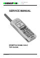
Product: TDP-52-SN3 / 27.1.1999 SERVICE MANUAL BENEFON SIGMA GOLD TDP-52-SN3 Dp_52ngbTOC.
Product: TDP-52-SN3 / 27.1.1999 TDP-52-SN3 1.0 GENERAL . . . . . . . . . . . . . . . . . . . . . . . . . . . . . . . . . . 1 - 1 1.1 TECHNICAL INFORMATION . . . . . . . . . . . . . . . . . . . . 1 - 1 1.1.1 Operational System . . . . . . . . . . . . . . . . . . . . . . . . . . . . . . . . . . 1 - 1 1.1.2 Dimensions . . . . . . . . . . . . . . . . . . . . . . . . . . . . . . . . . . . . . . . . 1 - 1 1.1.3 Power Consumption . . . . . . . . . . . . . . . . . . . . . . . . . . . . . . . . . . 1 - 1 1.1.
Product: TDP-52-SN3 / 27.1.1999 4.0 SERVICE APPLICATIONS . . . . . . . . . . . . . . . . . . . . . 4 - 1 4.1 BeneWin SCA-50 . . . . . . . . . . . . . . . . . . . . . . . . . . . . . 4 - 1 4.1.1 Installation of BeneWin program . . . . . . . . . . . . . . . . . . . . . . . . 4 - 1 4.1.2 To start the BeneWin program . . . . . . . . . . . . . . . . . . . . . . . . . . 4 - 3 4.2 Beneloc . . . . . . . . . . . . . . . . . . . . . . . . . . . . . . . . . . . . 4 - 4 4.2.1 Installation of Beneloc program . . . . .
Product: TDP-52-SN3 / 27.1.1999 5.3.1 General . . . . . . . . . . . . . . . . . . . . . . . . . . . . . . . . . . . . . . . . . . 5 - 36 5.3.2 Functional Description . . . . . . . . . . . . . . . . . . . . . . . . . . . . . . . 5 - 36 5.3.3 Control- and Output-Signals . . . . . . . . . . . . . . . . . . . . . . . . . . . 5 - 36 5.3.4 General . . . . . . . . . . . . . . . . . . . . . . . . . . . . . . . . . . . . . . . . . . 5 - 37 5.3.5 Function Description . . . . . . . . . . . . . . . . . . . . . . . . .
Product: TDP-52-SN3 / 27.1.1999 7.4.6 Hook . . . . . . . . . . . . . . . . . . . . . . . . . . . . . . . . . . . . . . . . . . . . . 7 - 38 7.4.7 Parts list OO0009 . . . . . . . . . . . . . . . . . . . . . . . . . . . . . . . . . . . 7 - 39 7.4.8 Cradle . . . . . . . . . . . . . . . . . . . . . . . . . . . . . . . . . . . . . . . . . . . . 7 - 43 8.0 OFFICE SET . . . . . . . . . . . . . . . . . . . . . . . . . . . . . . . . 8 - 1 8.1 OFFICE SET DDS-50 . . . . . . . . . . . . . . . . . . . . . . . . .
Product: TDP-52-SN3 / General 27.1.1999 1.0 GENERAL General 1.1 TECHNICAL INFORMATION 1.1.1 Operational System NMT-450i 1.1.2 Dimensions Size: 58 x 153 x 26 mm Weight: 295 g 1.1.3 Power Consumption - Batteries: 5 x 1.2 V NiCd (or NiMH) - Sleep current: 2 mA - Standby current: 60 mA - Conversation mode, high power: app. 0.9 A - Conversation mode, low power: app. 0.4 A Charger: - automatic 1 h rapid charging for NiCd or NiMH batteries 1.1.
Product: TDP-52-SN3 / General 27.1.1999 - hand strap - belt clip 1.1.5 Ringing Tones Adjustable - type, five fixed, one changeable with BeneWin - volume - progressive or fixed Silent alert - short tone and ‘call coming’ text in the display 1.1.
Product: TDP-52-SN3 / General 27.1.1999 1.1.
Product: TDP-52-SN3 / General 27.1.1999 1.2 PRODUCT FAMILY - BENEFON SIGMA GOLD HANDPORTABLE TDP-52-SN3 - MAINS CHARGER CMA-50-230 - CIGARETTE LIGHTER CHARGER CCS 50-12 - LIGHT HOLDER KDC-50 - HANDS FREE CAR KIT This kit includes a charging holder KDS-50, carbox UDH-50, external antenna, loudspeaker and microphone for hands free function, car radio mute and external alert facility. - EXTERNAL HANDSET WITH HOLDER HDS-50 This is an optional accessory for the hands free car kit.
Product: TDP-52-SN3 / General 27.1.
Product: TDP-52-SN3 / General 27.1.
Product: TDP-52-SN3 / General 27.1.
Product: TDP-52-SN3 / General 27.1.
Product: TDP-52-SN3 / General 27.1.
2.0 OWNER’S MANUAL 1user_gb.
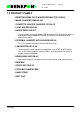
Product: TDP-52-SN3 / 27.1.1999 3.0 INSTALLATION INSTRUCTIONS 3.1 Phone Programming You can program Benefon Sigma Gold by using either the keys on your phone, or the BeneLoc computer program. In either case, you will need a localbox.
Product: TDP-52-SN3 / 27.1.1999 It is possible to program the sales date ONLY ONCE, which means that you will not be able to change it again afterwards. If the sales date has not been programmed, your phone will not enter the normal stand-by mode. 3.1.1.2 Radio Path Identification 1. Press , and the following text will appear in the display: RADIO PATH ID [XXXXXXXXXX]. 2. Choose CHANGE. Enter the radio path identification (ten digits), and save the identification by choosing SAVE.
Product: TDP-52-SN3 / 27.1.1999 GEN METER COM1 COM2 PHONE 3.1.2 To program Using the BeneLoc Program Start the installed program by clicking the icon. The phone must be connected to the system as discribed above. Main window Press Dealer-key to enter the programming window.
Product: TDP-52-SN3 / 27.1.1999 You can read the phone data by pressing the Read phone -key. You can change the miscellanous settings with the computer and transfer them to phone by pressing the Program phone -key. BeneLoc includes Help-program for further information.
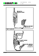
Product: TDP-52-SN3 / 27.1.1999 3.2 CAR KIT INSTALLATION The Car Kit includes a phone holder (KDS-50), a car box (UDH-50), an antenna, an installation base, a hf speaker, a microphone and a cable. The Car Kit sales package also includes an installation material bag, which contains the necessary installation equipment. On page 7 you will find a diagram of connections explaining how to install the Car Kit. 3.2.1 Antenna Choose a suitable place for the antenna.
Product: TDP-52-SN3 / 27.1.1999 3.2.6 Car Box UDH-50 Place the car box out of sight inside the dashboard of the car or to another place. First, connect the wires to the car box. Install the car box so, that the heat sink has some space for cooling. The car box has holes which enable you to fasten the car box with a cable tie. The installation material bag also contains adhesive band fasteners. 3.2.7 Hf Speaker Install the speaker in a suitable place near the floor of the car.
Product: TDP-52-SN3 / 27.1.1999 A Diagram of Connections How to install a cable to a carbox.
Product: TDP-52-SN3 / 27.1.1999 3.3 HF-FUNCTION Benefon Sigma Gold offers you two different hands free -setups for the Car Kit and Office Set: the background noise tuning (CAR KIT/OFFICE SET TUNING) and MIC-ERP contrast tuning (CAR KIT/OFFICE SET SWING). 3.3.1 CAR KIT TUNING/OFFICE SET TUNING (theory) You can set up the activation level of the microphone by using the CAR KIT TUNING option.
Product: TDP-52-SN3 / 27.1.1999 b. If the CAR KIT TUNING has been set up too low, the background noise in your car (2) will activate the microphone path, and the volume of the HFspeaker will be low. 50 (2) 40 Car kit tuning 30 c. When the CAR KIT TUNING has been set correctly only your voice (1 & 3) will open the microphone path. (1) (3) 50 Car kit tuning 40 30 (2) Benefon phones have been set in our factory so that they will function in most cars.
Product: TDP-52-SN3 / 27.1.1999 3.3.2 CAR KIT SWING/OFFICE SET SWING (theory) The four-step CAR KIT SWING/OFFICE SET SWING tuning is used to set the contrast of the microphone amplification/speaker attenuation swing. In the following figures the swing position while listening to the Car Kit or Office Set is indicated by a solid line and the position while speaking into Car Kit or Office Set the indicated by a dotted line. a.
Product: TDP-52-SN3 / 27.1.1999 3.3.3 HF-function tuning in practice You can tune HF-functions two ways: manually or with car kit. Manual tuning 1. Connect the localbox to your phone, and turn the phone on. 2. Press and the following text will appear in the display: ***BENEFON***. * will be flashing in the display. 3. Press , and the following text will appear in the display: HF-FUNCTION 4. Choose SELECT, and the following text will appear in the display: CAR KIT TUNING [038].
Product: TDP-52-SN3 / 27.1.1999 4.0 SERVICE APPLICATIONS 4.1 BeneWin SCA-50 The BeneWin SCM Program for Windows is designed to facilitate maintenance of phone numbers and user settings on Benefon mobile phones. You can also use your phone to carry out the commands in the BeneWin Program, but it is handier to process data using your screen and keyboard - the advantage of the BeneWin Program.
Product: TDP-52-SN3 / 27.1.1999 In the Command Line box, type the letter A: or B: to indicate your floppy disk drive, and then type SETUP. For example, A:SETUP. Click the OK button, and follow the instructions displayed on your screen. First, accept the location of the source files, which is the floppy disk drive you used for Setup. To continue Setup, choose the Continue button. To quit Setup, choose the Exit Setup button.
Product: TDP-52-SN3 / 27.1.1999 4.1.2 To start the BeneWin program Connect your phone with a cable to the serial port of your computer, which is called COM1 or COM2. The serial ports are located in the back of your computer, and more precise instructions can be found in the manual accompanying the computer. Plug the flat end of the cable into the connector at the bottom of your phone. When the cable has been connected and the phone is functioning, you can start the BeneWin Program.
Product: TDP-52-SN3 / 27.1.1999 4.2 Beneloc 1 ABC 3 GHI 5 JKL 6 7 PQRS 8 TUV 9 4 2 DEF MNO WXYZ 0 RM HF power 5V log gen flash 5V log meter BeneLoc program is designed to help service person on tuning and service purpose. With BeneLoc Program you will also get WinFlash Program. With WinFlash Program you can change the software to Benefon phones. Both, BeneLoc and WinFlash program will need Local Box with service rights to work. 4.2.1 Installation of Beneloc program Start Windows.
Product: TDP-52-SN3 / 27.1.1999 The Setup Program will ask you to specify the drive and directory in which you want to install the Beneloc Program. The Program suggests the following: C:\BeneApp\BeneLoc. Accept the drive and directory by clicking Next button. You can also type your own directory for Beneloc Program. The Setup Program creates all necessary directories and subdirectories to your computer. Setup Program also creates its own group window in Program Manager.
Product: TDP-52-SN3 / 27.1.1999 4.2.3 Using the BeneLoc program In the main window of the BeneLoc, you will find submenus and buttons. Clicking the buttons you can go to the submenus. Change For changing phone to another similar you do not need to do more than enter into main menu. It means that this button is not needed. If you are going to change the tested phone to one having different software in, clicking Change will start the registration protocol again.
Product: TDP-52-SN3 / 27.1.1999 Tunings From Tunings main menu you can select different tunings to do. Every tuning have they own instruction window. Follow given instructions to do tunings. Clicking START will start tuning. The value will be stored only by clicking SAVE. Some of the tunings are chained and you can enter to next phase by clicking NEXT. System You select used mobile phone system from this submenu. File From settings submenu you can manually change settings of the communication port. 4.
Product: TDP-52-SN3 / 27.1.1999 4.3.2 Using the WinFlash program You will find all Benefon mobile phone softwares installed to your computer from window in the left side. Select the software you want to transfer to phone by clicking it. In the right side window you will find some information of the selected software. Click Execute to start software transferring to phone. Follow the instructions shown in the screen.
MF 1502 A AM 0062 Version Nordic, Poland 7DP_52GB Black Blue Red Grey Green Wooden effect Color YA0070 Code A MC0836 MC0837 MC0840 MC0838 MC0839 MC0841 B MC0806 MC0808 MC0810 MC0812 MC0814 MC0824 Code Nordic Poland AV 0001 Version D OD0725 OD0785 F OY0725 OY0785 Code NC 2108 dg0102.ds4 Product: TDP-52-SN3 (Sigma Gold) / 27.1.1999 5.
Product: TDP-52-SN3 (Sigma Gold) / OA0701 Processor 27.1.1999 5.1 LOGIC / AUDIO OA0701 Processor Processor 5.1.1 General The entire radio audio and processor functions are found within a single PA0700 board, through which all other modules are connected. Only the RF signals have a different path and the keyboard has a different unit. The processor controls the audio and radio modules, internal devices and external accessories.
Product: TDP-52-SN3 (Sigma Gold) / OA0701 Processor 27.1.1999 5.1.2 Connectors: 5.1.2.
Product: TDP-52-SN3 (Sigma Gold) / OA0701 Processor 27.1.1999 16 17 18 19 20 21 22 23 24 25 26 27 28 29 30 GND GND GND GND GND XKEYINP0 XKEYINP1 XKEYINP2 XKEYINP3 XKEYINP3 XKEYOUT0 XKEYOUT1 XKEYOUT2 XKEYOUT3 XCHGIND 31 XBMEM 32 33 34 35 36 37 38 39 40 4A0701GB.
Product: TDP-52-SN3 (Sigma Gold) / OA0701 Processor 27.1.1999 5.1.2.3 Display Module, A101 1 2 3 4 5 6 7 8 9 10 11 12 13 14 15 16 VCC RES CSI AO SCL SI GND CONT GND LED KEYOUT1 KEYINP4 KEYINP4 KEYOUT0 PWRKEY GND supply voltage reset-line display data input 5V 0/5V 0/5V clock line for data 0/5V ground not function supply voltage for led of display key matrix output (volume key -) 0/5V key matrix input (volume keys+/-) 0/5V key matrix output (volume key +) 0/5V powerkey 5.1.2.
Product: TDP-52-SN3 (Sigma Gold) / OA0701 Processor 27.1.1999 5.1.3.1 Circuit Diagram Contents OA0701A OA0701B OA0701C OA0701D OA0701E module connector pins power supply cpu, ASIC, RAM, EPROM audio parts SIS-function 5.1.4 Functions 5.1.4.1 CPU I304 is itself a processor circuit. It is comprised of CPU, 512*8bit EEPROM, timers, A/D converters, and both series- and parallel I/O lines. The clock oscillator is located in the audio circuit and provides the CPU with a 7.2 MHz clock signal.
Product: TDP-52-SN3 (Sigma Gold) / OA0701 Processor 27.1.1999 5.1.4.2 Memories Memory and external I/O-circuit address coding is done with the ASIC circuit I305. The circuit options CSR, CSP, and OE are 0-active. The program memory is in 256k*8 EPROM. The program uses the addresses 2100H...FFFFH. Page selection makes available another similar memory block. RAM-memory is 8k*8 CMOS RAM at the addresses 0000H...1FFFH.
Product: TDP-52-SN3 (Sigma Gold) / OA0701 Processor 27.1.1999 5.1.4.7 RESET The processor voltage regulator ERROR output resets (stops) the processor and zeroes the controls when the battery voltage drops below 5V. When the voltage rises again, the processor restarts. 5.1.4.8 Power Switch The power switch (PWRKEY) is grounded, and directs the regulator I201 to conduct when pressed.
Product: TDP-52-SN3 (Sigma Gold) / OA0701 Processor 27.1.1999 5.1.4.12 Power Adjustment The transmitter control logic switches TX power and also adjusts it to the correct level. The STX_REG signal sets the transmitter to ready mode. Power is controlled by the ASIC analog output D/A 1. It is a pulse frequency modulated output which is converted to a DC voltage by integrating it with C379. 0V corresponds to "no power" state, and 5V to maximum transmitter power.
Product: TDP-52-SN3 (Sigma Gold) / OA0700 Audio 27.1.1999 Audio 5.1.5 Function Description OA0700 Audio The audio module is comprised of the following functions: 1. TX-audio signal handling 2. RX-audio signal handling 3. Fii signal handling 4. FFSK modem 5. DTMF generator/receiver 6. Signal level detectors 7. Compander 8. Expander 9. Buzzer The audio functions are mainly located in a single circuit AK2339. This chip from AKM is controlled by a serialbus.
Product: TDP-52-SN3 (Sigma Gold) / OA0700 Audio 27.1.1999 transmit signal. VR3 is a maximum deviation gain control circuit to set the transmit signal level. After the VR3 comes switch TXAUDON, which mutes the tx-audio signal using the TXMUTE control. From the switch, the signal is fed to the summing junction (ADD3) of the tx-audio signal, FFSK signal and Fiisignal. Next comes VR4 gain control circuit to set. SMF1 is smoothing filter for tx-audio signal.
Product: TDP-52-SN3 (Sigma Gold) / OA0700 Audio 27.1.1999 detection level standard. Once the detector judges a valid FFSK signal, ’H’ signal is put out on the FFSKDET pin (pin43). The data detector speed is determined by the external condensator C438. FFSK DEMOD. To recover 1200bps receive data and clock from the FFSK signal fed on DEM1 pin. The modem is connected to the CPU by series lines, the receiver to a synchronised gate, and transmission is directed to an ASIC series output.
Product: TDP-52-SN3 (Sigma Gold) / OA0700 Audio 27.1.1999 5.1.14 Audio signals for answer module The record signal comes from the tx side through the switch AUDLOOPON, ADD4, VR11 and AMP5 to answer module I101. The audio signal from the answer module comes to the summing junction AMP6. 5.1.15 The other in audio asic (I405) OSC is the main oscillator and clock divider for the prosessor. CLKBUF is clock buffer generate clock out from main clock.
Product: TDP-52-SN3 (Sigma Gold) / OA0701 Proc./ 27.1.1999 5.1.16 Parts list OA0701 OA0701 Proc./Audio CODE PART DESCRIPT. VALUE MANUF.
Product: TDP-52-SN3 (Sigma Gold) / OA0701 Proc./ 27.1.
Product: TDP-52-SN3 (Sigma Gold) / OA0701 Proc./ 27.1.
Product: TDP-52-SN3 (Sigma Gold) / OA0701 Proc./ 27.1.
Product: TDP-52-SN3 (Sigma Gold) / OA0701 Proc./ 27.1.1999 CODE RF0105 RF0102 RF0102 RF0102 RF0104 RF0103 RF0103 RF0103 RF0103 RF0103 VN0017 VM0220 X32765 X14400 PA0700 PART R459 R501 R502 R503 R510 R511 R512 R513 R514 R515 V101 V102 X305 X401 Y7 DESCRIPT. SMD resistor SMD resistor SMD resistor SMD resistor SMD resistor SMD resistor SMD resistor SMD resistor SMD resistor SMD resistor SMD B/B-connector SMD connector male SMD Crystal SMD crystal PCB for OA0700 VALUE 1 M 5% 0.125 W 1 k 5% 0.
Product: TDP-52-SN3 (Sigma Gold) / OA0701 Proc./ 27.1.1999 The Top Side Layout PA0700 A5 4A0701GB.
Product: TDP-52-SN3 (Sigma Gold) / OA0701 Proc./ 27.1.1999 The Bottom Side Layout PA0700 A5 4A0701GB.
4A0701GB.
Product: TDP-52-SN3 (Sigma Gold) / OA0701 Proc./ 48 NC 47 PD0 46 IRQ 45 XIRQ 44 NC 43 RESET 42 AD7 41 AD6 40 AD5 39 AD4 38 AD3 37 AD2 36 AD1 35 NC 34 AD0 33 XTAL 27.1.
Product: TDP-52-SN3 (Sigma Gold) / OA0701 Proc./ 27.1.1999 4A0701GB.
Product: TDP-52-SN3 (Sigma Gold) / OA0701 Proc./ 27.1.1999 4A0701GB.
Product: TDP-52-SN3 (Sigma Gold) / OA0701 Proc./ 27.1.1999 4A0701GB.
Product: TDP-52-SN3 (Sigma Gold) / OA0701 Proc./ 27.1.1999 4A0701GB.
Product: TDP-52-SN3 (Sigma Gold) / OA0701 Proc./ 27.1.1999 4A0701GB.
Product: TDP-52-SN3 (Sigma Gold) / OA0701 Proc./ 27.1.1999 4A0701GB.
Product: TDP-52-SN3 (Sigma Gold) / OH0700 27.1.1999 5.2 KEYBOARD OH0700 Keyboard 5.2.1 General Keyboard unit includes: key matrix, battery current measuring components, radio base connector, battery connectors and microphone. 5.2.2 Connectors: 5.2.2.
Product: TDP-52-SN3 (Sigma Gold) / OH0700 27.1.1999 31 32 33 34 35 36 37 38 39 40 BMEM MICINPUT ISIGN KEYLEDVB IVBDET V-PROG V-PROG input memory data-line from the bat- 0/5V tery nc nc microphone-line nc battery voltage course indicator 0/5V voltage for the led of keyboard 6V battery current indicator 0-5V battery charging voltage 5.2.2.
Product: TDP-52-SN3 (Sigma Gold) / OH0700 27.1.1999 5.2.3 Parts list OH0700 CODE PART DESCRIPT. VALUE MANUF.
Product: TDP-52-SN3 (Sigma Gold) / OH0700 27.1.1999 CODE AS0115 AS0115 AS0115 AS0115 AS0115 AS0115 CF0221 CF0223 CF0221 CF0221 CF0221 CF0221 CF0221 CF0221 CF0221 CF0221 CF0221 CF0221 VM0242 VM0017 VP0009 LF0061 LF0061 PH0700 PART S132 S133 S134 S135 S136 S137 T100 T101 T102 T103 T104 T105 T106 T107 T108 T109 T110 T111 V100 V101 V102 X100 X101 Y10 DESCRIPT.
Product: TDP-52-SN3 (Sigma Gold) / OH0700 27.1.1999 The Top Side Layout PH0700 A5 4H0700GB.
Product: TDP-52-SN3 (Sigma Gold) / OH0700 27.1.1999 The Bottom Side Layout PH0700 A5 4H0700GB.
Product: TDP-52-SN3 (Sigma Gold) / OH0700 27.1.1999 4H0700GB.
Product: TDP-52-SN3 (Sigma Gold) / Synthesizer 27.1.1999 5.3 RF MODULE RX Synthesizer Synthesizer 5.3.1 General The RX synthesizer generates an upper side injection frequency for the receiver. The injection frequency is fed to the receiver’s first mixer. Operating voltage Current consumption Output level to the receiver Frequency range 4.75VDC 14 mA +1 dBm 540,25...544,725 MHz 5.3.2 Functional Description The RX injection frequency is generated with a phase locked loop.
Product: TDP-52-SN3 (Sigma Gold) / Synthesizer 27.1.1999 TX-Synthesizer 5.3.4 General The TX synthesizer generates the final modulated transmission frequency, which is fed to the transmitter. Operating voltage Current consumption Output level to the transmitter Frequency range 4.75VDC <30 mA +6 dBm 453.000...457.475 MHz 5.3.5 Function Description The TX frequency is generated with a phase locked loop (PLL).
Product: TDP-52-SN3 (Sigma Gold) / Synthesizer 27.1.1999 5.3.6 Control- and Output-Signals VTXS TXAUDIO 12.8M SCLK SDATA SLE TXINJ AFC TXS_REG 4Z0700GB.__2 TX synthesizer operating voltage (4.75V) Transmitter audio signal 12.8 MHz signal to the receiver circuit.
Product: TDP-52-SN3 (Sigma Gold) / OY0725 27.1.1999 Receiver OY0725 Receiver 5.3.7 General The module contains all FM-receiver functional blocks. RF-amplifier 1. mixer 1. IF-amplifier FM IF system CF 739 double-balanced mixer CF 739 SA 607 includes the following blocks: 2. mixer IF limiter quadrature detector RSSI (received signal strength indicator) When the RF signal isreceived it is brought through the duplex filter to the amplifier stage Q101.
Product: TDP-52-SN3 (Sigma Gold) / OY0725 27.1.1999 5.3.8 Input- and Output-Signals RF input from the duplex filter RXINJ 12.8 MHz VRX 450 kHz RXAUDIO RSSI 463,000...467,475 MHz RX injection signal to the double balanced mixer 12.8 MHz signal to the multiplier for the 2.mixer RX operating voltage 4.75 V from the regulator Output from 2. IF to the AFC detector Receiver audio output 100mVrms Received signal strength indicator output 0,5...2V SENSITIVITY CHECK channel RF input SINAD psof.
Product: TDP-52-SN3 (Sigma Gold) / 27.1.1999 Transmitter OY0725Transmitter 5.3.9 General Operating voltage Current consumption Input level from the synthesizer Output level to the duplex filter Frequency range 5,7...8,0 VDC mid power max. 1.0 A low power max. 0.45 A +6 dBm mid power 33 dBm (2.0W) low power 24.7 dBm (0.3W) 453,000...457,475 MHz 5.3.10 Function Description The transmitter unit is comprised of three amplifier stages and two attenuator stages.
Product: TDP-52-SN3 (Sigma Gold) / OY0725-RF 27.1.1999 The Top Side Layout PY0700A3 OY0725-RF 4Z0700GB.
Product: TDP-52-SN3 (Sigma Gold) / OY0725-RF 27.1.1999 The Bottom Side Layout PY0700A3 4Z0700GB.
Product: TDP-52-SN3 (Sigma Gold) / OY0725-RF 27.1.1999 5.3.12 Parts list OY0725 OY0725-RF CODE PART DESCRIPT. VALUE MANUF.
Product: TDP-52-SN3 (Sigma Gold) / OY0725-RF 27.1.1999 CODE CF0101 CU3106 CC0223 CU0334 PART C328 C329 C341 C342 DESCRIPT. SMD capasitor SMD tantal SMD capasitor SMD tantalium capasitor VALUE 100 pF 5% 50 V NP0 10uF / 6V +-20% 22 nF 10% 50 V X7R 0.
Product: TDP-52-SN3 (Sigma Gold) / OY0725-RF 27.1.
Product: TDP-52-SN3 (Sigma Gold) / OY0725-RF 27.1.
Product: TDP-52-SN3 (Sigma Gold) / OY0725-RF 27.1.
Product: TDP-52-SN3 (Sigma Gold) / OY0725-RF 27.1.1999 CODE QA4931 PART Y421 DESCRIPT. SMD RF-tarnsistor VALUE NPN 9GHz/NF1.2dB/G13dB MANUF. Sanyo TYPE 2SC4931-B2 Last update 22.01.
Product: TDP-52-SN3 (Sigma Gold) / OY0725-RF 27.1.
Product: TDP-52-SN3 (Sigma Gold) / OY0725-RF 27.1.
Product: TDP-52-SN3 (Sigma Gold) / OY0725-RF 27.1.
26.1.1999 6.0 CHARGING CHARGING 8HAR_GB.
Product: CMA-50-230 (Mains Charger) / 27.1.1999 6.1 MAINS CHARGER CMA-50-230 The charger provides functions for charging Benefon brand mobile phones from a mains supply. Connector A YO0240 YC0055 CONNECTOR A 1 8CMA50GB_fm5.f 16 PIN CONFIGURATION: 1,2 charge current 3-5 nc 6,7 ground 8 - 15 nc 16 control voltage max.
Product: CCS-50-12 (Light Socket Charger) / 27.1.1999 6.2 LIGHTER SOCKET CHARGER CCS-50-12 The charger includes functions for using the handportable and for charging its batteries from the car battery. Connector A YO0243 YC0058 CONNECTOR A 1 8CCS50GB_fm5.f 16 PIN CONFIGURATION: 1,2 charge current 3-5 nc 6,7 ground 8 - 15 nc 16 control voltage max.
26.1.1999 7.0 CAR ASSEMBLY KIT CAR ASSEMBLY KIT 8CARA_GB.
Product: UDH-50 (Carbox) / YO0702 27.1.1999 7.1 CARBOX UDH-50 YO0702 7.1.1 Including attached functions - power supply filter - voltage regulators - processor controlled battery charger - controls for external relays (AL, MUTE) - handsfree amplifiers - PC/AUX-connector - handset connector - integrated branching unit 7.1.2 Connector descriptions 7.1.2.1 EXTVB V100 1 MUTE 2 GND 3 GND 4 AL 5 HF_SPKR 6 VBATT 8udh50gb_fm5.
Product: UDH-50 (Carbox) / YO0702 27.1.1999 7.1.2.2 HANDSET V102: 1 2 3 4 HS_ERP EGND MGND HS_MIC Audio signal for earphone + HOOK-signal HS Microphone signal to carbox 7.1.2.3 EXTMIC V103 1 2 3 4 5 GND NC HFMIC GND NC ground not connected HF Microphone signal to carbox ground not connected 7.1.2.4 PC/AUX V104 1 2 3 4 5 6 7 8 9 10 11 12 13 14 15 16 8udh50gb_fm5.
Product: UDH-50 (Carbox) / YO0702 27.1.1999 7.1.2.5 BOX V105 1 2 3 4 5 6 7 8 9 10 11 12 13 14 15 V_CHARGE V_CHARGE V-BAT NC EXTMIC GND GND EXTERP CADET I2CINT SCL SDA TXD RXD EXTIO 16 CHGCONT battery charging current battery charging current battery voltage not connected external microphone signal ground ground external ERP-signal carbox detection I2C interrupt I2C clock I2C data RS 232 RS 232 extra-IO charging control from the processor max. 2A / 9V 400 mV RMS 200 mV RMS +5V 7.1.2.
Product: UDH-50 (Carbox) / OO0700 27.1.1999 7.1.3 Parts list OO0700 OO0700 CODE PART DESCRIPT. VALUE MANUF.
Product: UDH-50 (Carbox) / OO0700 27.1.1999 CODE CE0476 CD0104 CU1106 CU0225 CH0105 CH0105 CH0105 CH0105 CH0105 CD0101 CD0104 CH0105 CH0105 CU0225 CU1106 CD0104 CE0337 CE0476 CE0337 CD0104 CD0103 CU0105 DT0033 PART C415 C416 C417 C418 C419 C420 C421 C430 C431 C440 C441 C460 C461 C462 C463 C464 C465 C466 C467 C468 C469 C480 D100 DESCRIPT.
Product: UDH-50 (Carbox) / OO0700 27.1.
Product: UDH-50 (Carbox) / OO0700 27.1.1999 CODE VN0003 VN0005 VM0242 VM0116 OW0022 LF0061 LF0061 PART V102 V103 V104 V105 V106 X100 X101 DESCRIPT. Modular jack Stereo jack SMD system connector Contact strip angle Charger module SMD EMI suppression filt SMD EMI suppression filt VALUE 4-pin 3.5mm 1x16 pin 2x8 6V/2A 4700pF/2A 1.6x6.8mm 4700pF/2A 1.6x6.8mm MANUF. AMP Zupami AMP NB-electr. Powerfinn Murata Murata TYPE 215875-1 3.5 EJW-C386 188227-1 H4-6-16G NFM61R30T472 NFM61R30T472 Last update 14.05.
Product: UDH-50 (Carbox) / OO0700 27.1.1999 The Top Side Layout PW0700B2 8udh50gb_fm5.
Product: UDH-50 (Carbox) / OO0700 27.1.1999 The Bottom Side Layout PW0700B2 8udh50gb_fm5.
Product: UDH-50 (Carbox) / OO0700 27.1.1999 A2 8udh50gb_fm5.
Product: UDH-50 (Carbox) / OO0700 27.1.1999 A2 8udh50gb_fm5.
Product: UDH-50 (Carbox) / OO0700 27.1.1999 A2 8udh50gb_fm5.
Product: UDH-50 (Carbox) / OO0700 27.1.1999 A2 8udh50gb_fm5.
Product: UDH-50 (Carbox) / YO0702 / Mechanics 27.1.1999 YO0702 / Mechanics MF 1502 MD 0702 NC 2008 8 pcs OO 0700 NC 2066 NG 1015 NF 0200 2 pcs NG 0011 NC 2010 NG 0012 MF 1140 MD 0703 UDH-50 Carbox YO0702 8udh50gb_fm5.
Product: UDH-50 (Carbox) / YO0704 27.1.1999 7.2 CARBOX UDH-50 YO0704 7.2.1 Including attached functions - power supply filter - voltage regulators - processor controlled battery charger - controls for external relays (AL, MUTE) - handsfree amplifiers - PC/AUX-connector - handset connector - integrated branching unit 7.2.2 Connector descriptions 7.2.2.1 EXTVB V100 1 MUTE 2 GND 3 GND 4 AL 5 HF_SPKR 6 VBATT 8UDH50GB.
Product: UDH-50 (Carbox) / YO0704 27.1.1999 7.2.2.2 HANDSET V102: 1 2 3 4 HS_ERP EGND MGND HS_MIC Audio signal for earphone + HOOK-signal HS Microphone signal to carbox 7.2.2.3 EXTMIC V103 1 2 3 4 5 GND NC HFMIC GND NC ground not connected HF Microphone signal to carbox ground not connected 7.2.2.4 PC/AUX V104 1 2 3 4 5 6 7 8 9 10 11 12 13 14 15 16 8UDH50GB.
Product: UDH-50 (Carbox) / YO0704 27.1.1999 7.2.2.5 BOX V105 1 2 3 4 5 6 7 8 9 10 11 12 13 14 15 V_CHARGE V_CHARGE V-BAT NC EXTMIC P_GND GND EXTERP CADET I2CINT SCL SDA TXD RXD EXTIO 16 CHGCONT battery charging current battery charging current battery voltage not connected external microphone signal ground ground external ERP-signal carbox detection I2C interrupt I2C clock I2C data RS 232 RS 232 extra-IO charging control from the processor max. 2A / 9V 400 mV RMS 200 mV RMS +5V 7.2.2.
Product: UDH-50 (Carbox) / OW0700 27.1.1999 7.2.3 Parts list OW0700 OW0700 CODE PART DESCRIPT. VALUE MANUF.
Product: UDH-50 (Carbox) / OW0700 27.1.
Product: UDH-50 (Carbox) / OW0700 27.1.1999 CODE DT0033 PART D100 DESCRIPT.
Product: UDH-50 (Carbox) / OW0700 27.1.
Product: UDH-50 (Carbox) / OW0700 27.1.1999 CODE RC0108 RD0332 RD0103 RD0153 RD0150 RC0108 RD0102 RD0104 RD0154 RD0471 RD0123 RD0103 RD0103 RD0563 RD0103 RD0393 RD0104 RD0103 RD0685 RD0274 RD0105 RD0102 RD0104 RD0105 RD0105 RD0104 RD0102 RD0274 RD0683 LT0005 VW0106 VN0003 VN0005 VM0242 VM0116 LF0061 LF0061 PART R501 R510 R511 R520 R530 R531 R532 R533 R534 R540 R541 R542 R543 R544 R545 R546 R547 R548 R549 R550 R551 R552 R553 R554 R555 R556 R557 R558 R559 T530 V100 V102 V103 V104 V105 X100 X101 DESCRIPT.
Product: UDH-50 (Carbox) / OW0700 27.1.1999 The Top Side Layout PW0700A5 8UDH50GB.
Product: UDH-50 (Carbox) / OW0700 27.1.1999 The Bottom Side Layout PW0700A5 8UDH50GB.
Product: UDH-50 (Carbox) / OW0700 27.1.1999 A5 8UDH50GB.
Product: UDH-50 (Carbox) / OW0700 27.1.1999 A5 8UDH50GB.
Product: UDH-50 (Carbox) / OW0700 27.1.1999 A5 8UDH50GB.
Product: UDH-50 (Carbox) / OW0700 27.1.1999 A5 8UDH50GB.
Product: UDH-50 (Carbox) / OW0700 27.1.1999 A5 8UDH50GB.
Product: UDH-50 (Carbox) / YO0704 / Mechanics 27.1.1999 YO0704 / Mechanics MF 1502 MD 0702 NC 2008 8 pcs OW 0700 NC 2066 NG 1015 NF 0200 2 pcs NG 0011 NC 2010 NG 0012 MF 1140 MD 0703 UDH-50 Carbox YO0704 8UDH50GB.
Product: UDH-50 (Carbox) / System cable YC1304 27.1.1999 7.2.4 System Cable System cable YC1304 1300 41.0 F5.
Product: KDS-50 (Hands-free Cradle) / YO0701 27.1.1999 7.3 HANDS-FREE CRADLE KDS-50 YO0701 7.3.1 Mechanics 8kds50gb_fm5.
Product: KDS-50 (Hands-free Cradle) / YO0701 27.1.1999 7.3.2 Module OO0702 The Top Side Layout PO0702A0 The Bottom Side Layout PO0702A0 8kds50gb_fm5.
Product: KDS-50 (Hands-free Cradle) / YO0701 27.1.1999 KDS-50 8kds50gb_fm5.
Product: HDS-50 (Ext. Handset With Cradle) / 27.1.1999 7.4 EXTERNAL HANDSET WITH CRADLE HDS-50 7.4.1 External Handset (not serviceable) 7.4.1.1 Mechanics External Handset HDS-50 YH0442 8HDS50GB_fm5.
Product: HDS-50 (Ext. Handset With Cradle) / 27.1.1999 7.4.1.2 Cable 1500 4 F14 1 X 360 COILED FLAT CABLE (4.8x2.6) 4 POS.
Product: HDS-50 (Ext. Handset With Cradle) / 27.1.1999 7.4.3 Connector XIN Signals 1 2 3 4 ERP GND GND MIC earphone input, HOOK state ground ground microphone output 7.4.4 Microphone Sensitivity: -43 dB ± 6 dB Vendor and part no: Hosiden KUC2023 or KUB2023 33 pF; Size: 0805; Mounted on the microphone element. RF decoupling capacitor: 7.4.5 Speaker Sensitivity 95 dB ± 5 dB Vendor and part no: Impedance: Resistance (DC): Hosiden KDR0928-IE-0030 min 120 ohm max 3 kohm 7.4.
Product: HDS-50 (Ext. Handset With Cradle) / 27.1.1999 7.4.7 Parts list OO0009 CODE PART DESCRIPT. VALUE MANUF. TYPE CU0475 CD0221 CD0221 CD0221 CD0221 PO0009 RP0222 RD0222 AR0016 AE0018 AM2024 VM0204 C106 C108 C110 C112 C114 M100 R100 R102 S102 XERP XMIC XIN SMD tantal SMD capasitor SMD capasitor SMD capasitor SMD capasitor PCB for OO0900 Edge control pot. SMD resistor Reed-relay Assembled earphone unit Assembled microphone unit Contact strip angle 4.7uF/16V 20% 4.7X2.
Product: HDS-50 (Ext. Handset With Cradle) / 27.1.1999 The Top Side Layout PO0009A1 (Schematic OO0009A1) 8HDS50GB_fm5.
Product: HDS-50 (Ext. Handset With Cradle) / 27.1.1999 The Bottom Side Layout PO0009A1 (Schematic OO0009A1) 8HDS50GB_fm5.
Product: HDS-50 (Ext. Handset With Cradle) / HLS-41, HDS-50, HXS-40 27.1.1999 8HDS50GB_fm5.
Product: HDS-50 (Ext. Handset With Cradle) / 27.1.1999 7.4.8 Cradle 7.4.8.1 Mechanics 8HDS50GB_fm5.
27.1.1999 8.0 OFFICE SET OFFICE SET 8OSET_GB.
Product: DDS-50(Office set) / YO0311 27.1.1999 8.1 OFFICE SET DDS-50 YO0311 8.1.1 General Main features of the office set are: - Hands Free microphone and speaker - Handset - connection for external antenna - intelligent charge functions for both the phone battery and the spare battery - connection for additional accessories Office set DDS-50 The office set is designed to make the use of the mobile phone easier and more effective both at home and at the workplace.
Product: DDS-50(Office set) / YO0311 27.1.1999 8.1.2 Connectors 8.1.2.1 Main module OO0303 AUX/PWR_IN_1, AUX/PWR_IN_2 PIN # 1,2 3 4 5 6,7 8 9 10 11 12 13 14 15 16 NAME VB PH_VOLT nc AUX_MIC GND AUX_ERP nc I2CINT SCL SDA TxD RxD nc VB_CTRL PIN # 1 2 3 4 5 6 7 8 NAME GND HS_MIC HS_ERP PH_R PH_G B_R B_G SWITCH DESCRIPTION power in mobile battery voltage LEVEL max.
Product: DDS-50(Office set) / YO0311 27.1.1999 V4 PIN # 1 2 3 4 5 6 7 8 9 10 11 12 NAME V_CHG V_BATT EXTMIC GND EXTERP CADET I2CINT SCL SDA TxD RxD PH_CTRL DESCRIPTION charge current for phone mobile battery voltage microphone signal ground earphone signal office kit indicator for phone LEVEL max. 10 V, 1.5 A charger control from phone PIN # NAME I_BATT DESCRIPTION charge current for battery LEVEL max. 10 V, 1.
Product: DDS-50(Office set) / YO0311 27.1.1999 V10 PIN # 1 2 NAME HF_SPKR GND DESCRIPTION Hands Free speaker ground LEVEL 8.1.2.
Product: DDS-50(Office set) / YO0311 27.1.1999 V2 PIN # 1,2 3 4 5 6,7 8 9 10 11 12 13 14 15 16 8dds50gb_fm5.fm NAME V_CHG V_BATT nc EXTMIC GND EXTERP CADET I2CINT SCL SDA TxD RxD nc PH_CTRL DESCRIPTION charge current for phone mobile battery voltage microphone signal ground earphone signal office kit indicator for phone I2C bus interrupt I2C bus clock I2C bus data RS-232 TxD RS-232 RxD power supply control LEVEL max. 10 V, 1.
Product: DDS-50(Office set) / YO0311 27.1.1999 8.1.3 Operation 8.1.3.1 General Power supply unit is connected to one of the connectors on the back of the unit. Connections on these two connectors are identical to each other. Supply voltage (VB) turns on regulator I124 which is used to generate +5 VDC supply (VCC) for processor and other electronics. Note that the power amplifiers of the earphone signal, I499 and I528 do not use VCC but VB instead.
Product: DDS-50(Office set) / YO0311 27.1.1999 Spare battery discharge is controlled with signal D2. High level on output switches transistors Q287 and Q285 into conducting state, which makes current flow through resistors R280-283 and transistor Q285. Nominal value of discharge current is ~ 180 mA. Signal D3 is used to turn on/off the detect current supply I234. The logic high signal turns the regulator off and logic low on. When the phone is present, the state of this pin is usually low.
Product: DDS-50(Office set) / OO0303 27.1.1999 8.1.4 Parts list OO0303 (P3) OO0303 CODE PART DESCRIPT. VALUE MANUF.
Product: DDS-50(Office set) / OO0303 27.1.
Product: DDS-50(Office set) / OO0303 27.1.1999 CODE IA1905 PART I499 DESCRIPT.
Product: DDS-50(Office set) / OO0303 27.1.
Product: DDS-50(Office set) / OO0303 27.1.1999 CODE NI0508 VM0242 X80006 X80007 PO0300 NC2015 NC2015 NC2015 NC2015 NF0200 NF0200 NF0200 NF0200 PART V13 V3 X1 X261 Y15 Y16 Y17 Y18 Y19 Y20 Y21 Y22 Y23 DESCRIPT. Battery contact spring SMD system connector Crystal SMD crystal PCB for the office kit Cross recessed screw Cross recessed screw Cross recessed screw Cross recessed screw Nut Nut Nut Nut VALUE for DDS-40 1x16 pin 8.0000 MHz 8.000MHz Hold.
Product: DDS-50(Office set) / OO0303 27.1.1999 The Top Side Layout PO0300A0 The Bottom Side Layout PO0300A0 8dds50gb_fm5.
Product: DDS-50(Office set) / OO0303 27.1.1999 8dds50gb_fm5.
Product: DDS-50(Office set) / OO0303 27.1.1999 8dds50gb_fm5.
Product: DDS-50(Office set) / OO0303 27.1.1999 8dds50gb_fm5.
Product: DDS-50(Office set) / OO0301 27.1.1999 8.1.5 Parts list OO301 OO0301 CODE PART DESCRIPT. VALUE MANUF. TYPE CD0221 CD0221 CD0223 DLG155 DLG155 VN0005 AS0105 PO0301 C1 C2 C3 D1 D2 V2 V3 Y8 SMD capasitor SMD capasitor SMD capasitor SMD bicolor SMD bicolor Stereo jack Tact switch Connector PCB for office 220 pF 5% 50 V NP0 220 pF 5% 50 V NP0 22 nF 10% 50 V X7R Green/red 25mcd/20mA Green/red 25mcd/20mA 3.
Product: DDS-50(Office set) / OO0301 27.1.1999 8dds50gb_fm5.
Product: DDS-50(Office set) / OO0302 27.1.1999 8.1.6 Part list OO0302 OO0302 CODE PART DESCRIPT. VALUE MANUF. VN0242 PO0302 V2 Y1 SMD system conn. Flexible PCB for OO0302 (holder) DDS-40 AMP Simflex TYPE Last update 12.11.96 The Bottom Side Layout PO0302A1 8dds50gb_fm5.
Product: DDS-50(Office set) / OO0302 27.1.1999 8dds50gb_fm5.
Product: DDS-50(Office set) / OO0302 27.1.1999 8dds50gb_fm5.
Product: HXS-40 (External Handset) / 27.1.1999 8.2 EXTERNAL HANDSET HXS-40 8.2.1 External Handset (not serviceable) 8.2.1.1 Mechanics External Handset HXS-40 YH0443 8hxs40gb_fm5.
Product: HXS-40 (External Handset) / 27.1.1999 8.2.1.2 Cable 100 360 F 17±1 COILED FLAT CABLE (4.8x2.6) 4 POS. GND 24 AWG STRANDED WIRE, COLOR BLACK FLAT UNDERSIDE EAR +5 MIC CONNECTOR: 3.
Product: HXS-40 (External Handset) / 27.1.1999 8.2.3 Connector XIN Signals 1 2 3 4 ERP GND GND MIC earphone input, HOOK state ground ground microphone output 8.2.4 Microphone Sensitivity: -43 dB ± 6 dB Vendor and part no: Hosiden KUC2023 or KUB2023 33 pF; Size: 0805; Mounted on the microphone element. RF decoupling capacitor: 8.2.5 Speaker Sensitivity 95 dB ± 5 dB Vendor and part no: Impedance: Resistance (DC): Hosiden KDR0928-IE-0030 min 120 ohm max 3 kohm 8.2.
Product: HXS-40 (External Handset) / 27.1.1999 8.2.7 Parts list OO0009 CODE PART DESCRIPT. VALUE MANUF. TYPE CU0475 CD0221 CD0221 CD0221 CD0221 PO0009 RP0222 RD0222 AR0016 AE0018 AM2024 VM0204 C106 C108 C110 C112 C114 M100 R100 R102 S102 XERP XMIC XIN SMD tantal SMD capasitor SMD capasitor SMD capasitor SMD capasitor PCB for OO0900 Edge control pot. SMD resistor Reed-relay Assembled earphone unit Assembled microphone unit Contact strip angle 4.7uF/16V 20% 4.7X2.
Product: HXS-40 (External Handset) / 27.1.1999 The Top Side Layout PO0009A1 (Schematic OO0009A1) 8hxs40gb_fm5.
Product: HXS-40 (External Handset) / 27.1.1999 The Bottom Side Layout PO0009A1 (Schematic OO0009A1) 8hxs40gb_fm5.
Product: HXS-40 (External Handset) / HLS-41, HDS-50, HXS-40 27.1.1999 8hxs40gb_fm5.
27.1.1999 9.0 OTHER ACCESSORIES OTHER ACCESSORIES 8OTHE_GB.
Product: LIF-40 (Line Interface) / YO0245 27.1.1999 9.1 LINE INTERFACE LIF-40 YO0245 9.1.1 General The line interface is an accessory for a Benefon phone to enable a tele-device approved for the general network to be connected to the handportable. The teledevice should be approved for connection to a fixed line network. 9.1.1.1 Telefax devices and modems An error correcting modem (e.g. MNP, LAPM), and telefax (Level III or newer) are recommended for data transfer.
Product: LIF-40 (Line Interface) / YO0245 27.1.1999 When the dialling tone is heard, there is approx. 30 s. time to start dialling the number. The number may also be dialled from the handportable keyboard. 9.1.2.2 Answering a call with the tele-device. A call is answered normally by lifting the tele-device handset or allowing the device to answer automatically.
Product: LIF-40 (Line Interface) / YO0245 27.1.1999 9.1.3.1 TROUBLE SHOOTING When moving about or in an area with poor reception, radio fade and changes between base stations will interrupt radio contact. Typical symptoms of data transfer errors are random characters, missing characters, loss of contact, drop in data transfer speed, missing lines and error lines in telefaxes. The data transfer device and program should withstand momentary breaks.
Product: LIF-40 (Line Interface) / YO0245 27.1.1999 9.1.3.3 Connectors X120 1 2 3 4 5 6 7 EXTMIC GND EXTERp VBAT I2CDAT I2CCLK I2CINT MIC input for hand-portable Signal ground ERP output from hand-portable NiCd battery voltage I2C-connection data line I2C-connection clock line I2C-connection interrupt 400 mVrms 200 mVrms 7.2 V 0/5 V 0/5 V 0/5 V X121 1 2 LB LA Two-wire connection to data terminal 9.1.3.
Product: LIF-40 (Line Interface) / YO0245 27.1.1999 While Q100 is conducting, the energy flows through resistor R108 to the coil L100. When the switch Q100 stops conducting, the energy received by L100 is discharged through the rectifier diode D100 to the capacitor C106. The fet is protected by C122 and C123 against excessive voltage peaks, while L101/C107 functions as a lowpass filter for filtering the ripple voltage.
Product: LIF-40 (Line Interface) / YO0245 27.1.1999 9.1.4 Manufacturers Declaration for BABT/SITS/85/22 a) The electrical conditions present at the terminal apparatus connector are as follows: i) 5-10 VDC depending on the battery voltage of the portable ii) as above iii) ringing voltage 50 Vrms, f = 26 Hz maximum REN driving capability = 1 iv) free/reserved tone 430 Hz, I = 25 ±5 mA b) Maximum loop resistance of possible extension cable between line interface and terminal apparatus is 25 ohms.
Xo0245e4_fm5.fm TXAUDIO RXAUDIO SCL SDA IICINT VB I2C address 4AH PCF 8574 REG. +5V P2/400HZ_OFF OSCILLATOR/ DIVIDER (74HC4060) P4/HOOK_DET (+5V=ON HOOK) P1/PWR_OFF P0/RING_OFF Input: 5.5V - 10V Out: 15V +- 3V / 60V+- 10V 400Hz .220kHz 25Hz DC/DC Converter 4/2-WIRE AUDIO CONV. HOOK DET. LPF Title: Line interface Date: 21.4.1993 / HJo BENEF Current sink LA LB N Product: LIF-40 (Line Interface) / YO0245 27.1.
Product: LIF-40 (Line Interface) / OO0245 27.1.1999 9.1.5 Parts list OO0245 OO0245 CODE PART DESCRIPT. VALUE MANUF.
Product: LIF-40 (Line Interface) / OO0245 27.1.
Product: LIF-40 (Line Interface) / OO0245 27.1.1999 CODE RF0103 RF0104 RF0103 RF0103 RF0103 RF0223 RF0103 RF0223 RF0103 RF0275 RC0562 VR0407 PART R145 R146 R147 R148 R149 R150 R151 R152 R153 R201 R203 TEL DESCRIPT. SMD resistor SMD resistor SMD resistor SMD resistor SMD resistor SMD resistor SMD resistor SMD resistor SMD resistor SMD resistor SMD resistor Line conv.modular cable VALUE 10 k 5% 0.125 W 100 k 5% 0.125 W 10 k 5% 0.125 W 10 k 5% 0.125 W 10 k 5% 0.125 W 22 k 5% 0.125 W 10 k 5% 0.
Product: LIF-40 (Line Interface) / OO0245 27.1.1999 OO0245 Component Side Layout PO0245A0 Xo0245e4_fm5.
Product: LIF-40 (Line Interface) / OO0245 27.1.1999 Solder Side Layout PO0245A0 Xo0245e4_fm5.
Product: LIF-40 (Line Interface) / OO0245 27.1.1999 Xo0245e4_fm5.
Product: LIF-40 (Line Interface) / OO0245 27.1.1999 Xo0245e4_fm5.
Product: DB-40 (Branching Unit) / YO0236 27.1.1999 9.2 BRANCHING UNIT YO0236 Xo0236e4_fm5.
Product: DB-40 (Branching Unit) / YO0236 27.1.1999 9.2.1 General With the branching box you can simultaneously connect several accessories, such as an external handset and a line converter, to the car installation kit and the handportable. 9.2.2 Connectors 9.2.2.1 Connector PC/HS Signals 1 and 2 3 4 V-CHARGE +9V TXD 5 HSMIC 6and 7 8 9 10 11 12 GND HSERP RXD I2CINT SCL SDA 13 CHCONT 14 EXTIO Battery charging voltage 2 A in Operation voltage for accessories 0.
Product: DB-40 (Branching Unit) / YO0236 27.1.1999 9.2.2.3 Connector PC Signals 1 and 2 3 V-CHARGE 9V 5 PCMIC 6 and 7 GND 8 PCERP 10 11 12 13 14 I2CINT SCL SDA TXD RXD 16 CHCGONT Battery charging voltage 2 A in Operation voltage for accessories 0.
Product: DB-40 (Branching Unit) / OO0241 27.1.1999 9.2.4 Parts list OO0241 OO0241 CODE PART DESCRIPT. VALUE MANUF.
Product: DB-40 (Branching Unit) / OO0241 27.1.1999 OO0241 Component Side Layout PO0241A3 (Schematic OO0241A3) Xo0236e4_fm5.
Product: DB-40 (Branching Unit) / OO0241 27.1.1999 Solder Side Layout PO0241A3 (Schematic OO0241A3) Xo0236e4_fm5.
Product: DB-40 (Branching Unit) / OO0241 27.1.1999 Xo0236e4_fm5.