IB1100, IB850, IB600 Installation Manual NEW ZEALAND EDITION Important: The appliance shall be installed in accordance with; • This installation instruction booklet • Local gas fitting regulations • Municipal building codes • Electrical wiring regulations • AS 5601 / AG 601—2000, Gas installations / NZ5261:2003 Gas Installation • Any other relevant statutory regulations.
Note: THERE ARE FOUR MAIN THINGS TO CONSIDER BEFORE INSTALLATION • Cavity Dimensions & Clearances • Coupling of Flue to Fire • Coupling of Gas Lines to Fire • Fixing the Fire to the Cavity The sequences you choose to do these tasks will vary on your individual scenario. Please read these instructions fully before proceeding with your installation. Leave the installation of the fascia panels until the very end of the installation and commissioning to avoid damage to the fascia panels.
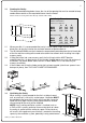
Contents: Section: • Product Description 1.0 • Creating the Cavity 2.0 • Ventilating the Cavity 3.0 • Cavity Base 4.0 • Hearth 5.0 • Raised Installations Up a Wall 6.0 • Wall Linings 7.0 • Mantle Clearance 8.0 • Television Clearance 8.1 • Corner Installations 9.0 • Power Supply 10.0 • Installing the Flue System 11.0 • Laying Gas Pipe 12.0 • Assembling the Outer Skin Kit (IB1100 Only) 13.0 • Fixing the Outer Skin Kit to the Cavity (IB1100 Only) 14.
1.0 Product Description: The Escea IB1100, IB850 and IB600 gas fires are designed to be built into a cavity. These appliances are flued conventionally via Ø100mm flue system. The user will control their fire with the Radio Frequency (RF) remote that will normally be left in its wall mount cradle. In addition to the RF remote it has a single auxiliary On/Off button on the unit. When not in operation it is in a standby mode unless it is physically isolated from the mains supply.
2.0 Creating the Cavity: The dimensioned drawing below shows the size of the opening that must be created to keep combustible materials at the required distance from the heater. Note: It is not necessary to line the side, top or back of the cavity. Ideal Cavity Dimensions: (Timber framed walls) All dimensions in millimetres IB600 IB850 IB1100 B A 700 965 1265 B 585 560 560 C 565 565 565 B 570 545 565 C 520 520 565 (Masonry Cavity) A C IB600 IB850 IB1100 A 600 950 1265 (Check offset.
effect on the gas fireplace. This may result in nuisance shut down and give an E3 error code on the handheld remote. IMPORTANT: For the power flue installation, a single Ø120mm hole, covered with a suitable louvre plate, centrally located at the base of the cavity is required. 3.1 It is also highly recommended to add some ventilation to the base of masonry cavities in the form of a group of 3 Ø20mm holes to let in fresh air. If this is on an external breastwork then cover with a suitable louvre plate.
8.0 Mantle Clearance: Please refer to the diagram on the previous page. Mantles or protruding ledges mounted above the heater that are made from combustible materials, must not extend outside of the dimensions shown. 8.1 Television Clearances: The following are the recommended minimum clearances for the location of any electrical equipment (such as Plasma TV, LCD TV or home theatre) above an Escea IB Series gas fire.
9.3 IB1100 minimum corner install dimensions: 1190mm 2380mm 1260mm 596mm 560mm 596mm 1683mm 10.0 10.1 10.2 Power Supply: Whilst the cavity is being created consideration should be given to appropriate location of a standard 3 pin, EARTHED 240V power outlet. This must be within 0.5m of the rear left hand corner of the appliance.
11.0 Installing the Flue System: Non-Masonry Timber Frame Cavity: The heater must be flued to the outside via Ø100mm stainless steel flue that is covered by a Ø150mm liner. This must be installed in accordance with the requirements of NZS5261 and local codes. The minimum flue length = 3.6m (This is the minimum vertical rise from the fire to the flue terminal.) The flue and liner must be supported 11.1 The top of the flue must be capped with an appropriate anti down draft cowl.
FROM NZS 5261:2003, please ensure compliance to all other relevant sections of this code. 2.6.13 FLUE TERMINALS 2.6.13.1 Location The termination point of a flue shall be located in relation to any associated building and to neighbouring structures so that wind from any direction is not likely to create a downdraught in the flue or chimney. Except where 2.6.13.
12.3 IB1100: The IB1100 Outer Skin Kit has 4 possible entry points for solid gas pipe, on the four corners of the kit. Each is sealed by a ‘knock-out’. Remove only the knock-out which you require, and place the supplied rubber plug into the hole. You will need to make a small cut into the rubber plug to allow the gas pipe to pass through, keeping the plug as air-tight as possible. 13.
13.2 Attach the Rear to the Sides and Base: The rear panel fits inside the Side and Base panels, make sure the flanges on the Side and Base panels are on the outside. The two holes on the Rear panel go towards the bottom. 13.3 Attach the Top-Rear: Attach the top-rear panel to the Sides and Rear panels, with the flanges of the Top-rear panel on the outside. Do not attach Top-Front panel yet, this will be done after the flue has been mated with the fire. 14.
15.0 Insert the Flue Support Bracket (IB1100 Only): Place the Flue Support Bracket in line with the flue hole on the Top-Rear panel. The Flue should be ready to pass through the hole in the OSK and mate with the Gas Fire Spigot. The Flue Liner should rest on top of the Flue Support Bracket and self locate. 16.0 Preparing the Heater for Installation: The spacer brackets on the top, sides and back of heater MUST be bent and re-fixed as per instructions in section 2.
Step 2: 18.0 Lift out glass and place it carefully aside. Connecting Flue to Heater: This is a 7 step process and is performed after the heater has been pushed into position in the cavity and before fascia panels have been fitted. 1) Remove glass as shown above. 2) Remove the log set and its associated packaging from the fire box. 3) Remove the top of the heater outer shell. Take out the screw from each side (as shown below) and pull the top of heater shell out towards yourself.
It should now be possible to reach up from inside of the heater and connect the flue to the heater’s flue spigot as per sections 18.1 and 18.2. This junction should be made fast with both sealant and a fixing screw. 18.1 18.2 Note: If installing a flue system into a framed timber wall the outer liner should not come down any further than onto the stand offs on the top of the heater to allow unimpeded flow of air between flue and liner.
20.0 Fixing the Heater to the Base and Wall: There are several ways that the heater can be fixed against movement: It is a requirement that this heater be securely fastened to the wall and base. Note: It is important that the outer fascia is used during this process to ensure that the heater is located in the appropriate position within the cavity. 21.0 Fixing Heater to Base: Please refer to 18.
22.0 IB850 & IB60- Locating the Log Set After Replacing the Fire Box: 1) Remove packaging from around log sets 2) Place rear log (long rectangular one) into position by inserting it in behind retainer brackets at rear of fire box. 3) Place the front log sets into position over the top of the main burners. Use the log template to properly locate the logs. The front edge of each log should have its front edge directly behind the holes in the top of each burner which should follow the contours of the logs.
IB850 Log & Template Position 4) Line up some of the coals that have been supplied with this appliance, along the burner holes in front of the logs. 5) Scatter the remaining coals around to fill the empty spaces left over.
22.1 IB1100- Locating the Log Set After Replacing the Fire Box: 1) Remove packaging from around log sets 2) Place 2 x rear logs (long rectangular ones) into position by inserting in behind retainer brackets at rear of fire box. 3) Place front three log sets into position over the top of the main burners. Use the log template to properly locate the logs.
22.2 Log Replacement: The fire unit should never be used with broken logs. Turn off the fire and allow the unit to cool before removing the glass to carefully remove the logs. If for any reason a log should need replacement, you must use the proper replacement log. The position of these logs must be as shown in the diagrams above. Note: Improper positioning of logs may create carbon build-up and will alter the unit’s performance.
pressures listed on the table below then reassess installation pipe size or upstream regulator settings. Replace inlet test point screw. 3) Remove the operating pressure test point screw. Connect manometer tube and measure pressure with heater running on full (all burners running) and with all the other gas appliances running. 4) The heater regulator pressure has been factory set to 1.0Kpa for Natural Gas heaters and 2.30Kpa for LPG heaters.
25.0 Fitting the Fascia Panels: To avoid scratches or knocks to the fascia panels of this heater they must be fitted at the complete conclusion of the installation process. It may be necessary to use the outer fascia to initially locate the heater but then remove it again so that there is no chance of damage. Note: Never Ever Rub the Fascia Panels.
25.1 When installing a 4 sided fascia ensure that the clips that the outer fascia screw into are at the bottom of the slot on which they are attached as shown below. The outer fascia should be pushed down onto the top lip so that it is as low as possible and the screw holes in the fascia line up with the lowered clips. Top lip 25.
27.0 Normal Operating Sounds and Smells; Note: Each time the fire is lit from cold the glass may fog up with condensation. This is normal and the condensation will disappear within a few minutes once the glass heats up. 27.1 Sounds It is possible that you will hear some sounds from your gas appliance. This is perfectly normal due to the fact that there various types of materials used within your appliance. Listed below are some examples.
28.0 Installation Check List: 1 Ensure there is adequate ventilation in the cavity. 2 Ensure the spark electrodes are correctly positioned. 3 Operating pressure checked with heater running on full (all burners operating) and all other gas appliances in the house switched on. 4 Flue Draw checked, 5 minutes after start up. 5 Logs in correct position. 6 Coals spread along front burner.