
Indoor Fireplace User Manual


G8860 _4 Installation Manual NZ
15
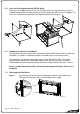
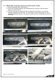
It should now be possible to reach up from inside of the heater and connect the flue to the
heater’s flue spigot as per sections 18.1 and 18.2. This junction should be made fast with
both sealant and a fixing screw.
18.1
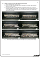
18.2 Note: If installing a flue system into a framed timber wall the outer liner should not come
down any further than onto the stand offs on the top of the heater to allow unimpeded flow of
air between flue and liner. Please ensure the weight of the liner is supported and not all
bearing down on the fire.
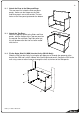
5) Replace the parts and panels that have been removed. The fire box must be completely
centralised before pushing it back into place otherwise the heat exchanger will not
engage with the draft diverter at the back of the appliance.
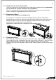
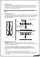
19.0 Connecting the Gas Pipe:
When the heater has been pushed back into position the 300mm flexible braided stainless
steel gas pipe (supplied) can be connected to the inlet side of the appliance regulator at the
front RH corner of the heater. The hose and pipe assembly should have already been tested
as per section 12.2.
19.1 If the installer chooses not to use the supplied flexible inlet pipe then 12mm copper can be
run directly to heater and connected onto the regulator with flare nut (BSP thread). The
regulator that is supplied with the fire MUST NOT BE REMOVED. Removal of the regulator,
or replacing it with one not intended for use with an Escea fire, will void the limited appliance
warranty.
Flue liner should seat
onto the stand off
brackets as shown.