Pyxis Lab Inc. ST-500 Inline Fluorometer Probe Instruction Manual Version 1.3 Pyxis Lab, Inc.
Contents 1. INTRODUCTION ............................................................................................................................................. 3 1.1. 2. ST-500 SERIES .................................................................................................................................................3 UNPACKAGING THE INSTRUMENT ................................................................................................................. 4 2.1. 2.2.
1. Introduction The Pyxis ST-500 inline fluorometer probe measures the concentration of fluorescence tracer PTSA (pyrenetetrasulfonic acid) in water. It can be simply inserted to the compression fitting port of a custom made tee. The companion tee has two ¾ inch female NPT ports and can be placed to an existing ¾ inch sample water line. The 4-20mA current output of the ST-500 probe can be connected to any controller that accepts an isolated or non-isolated 4-20mA input. The ST-500 probe is a smart device.
Model ST-500 ST-500B ST-500C Output and Main Features 4-20 mA current output, Modbus RTU via RS485, calibration via PC interface Data saving in the probe, saved data, error and warning messages downloadable via Modbus 4 digital inputs and 4 digital outputs Availability Available Firmware upgrade via a computer interface Send requests to service@pyxis-lab.com 2.
Cable Length: 5 feet, terminated with IP67 connectors Power consumption: 52 mA at 24 V Dimension: Length 6.8 inch (172.7 mm), body diameter 1.44 inch (36.6 mm) Weight: 0.46 pounds (210 grams) PTSA Range: 0 to 300 ppb (uncertainty ±1 ppb or 5% whichever is greater, 3 sigma) 4. Installation The ST-500 probe comes with a custom made tee. It is recommended that the tee is inserted to a pipe system to allow sample water to flow upwards vertically.
Follow the wiring table below to connect the ST-500 probe to a controller. The ST-500 probe is a three-wire, non-loop powered, 4-20mA device. It needs to be connected a 24 VDC power supplier. The negative 24V power wire (common) and the negative 4-20 mA wire (return) in the ST-500 probe are internally connected. The ST-500 probe 4-20mA output can be connected to an isolated or non-isolated 4-20mA input terminal in common water treatment controllers.
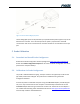
Do not connect the solution ground to the power ground! 4.2. Connection to a Computer and Other Devices 4.2.1. Connect to a computer Figure 3 shows the connection between a computer and the ST-500 probe via USB-RS485 adapter. Use the USB-RS485 adapter provided by Pyxis Lab Inc. (Item Number: MA-485). Insert the adapter between the two cable terminals. The controller side cable must be connected to the controller to provide power to the probe.
Figure 4. Connect to DC-200 graphic panel The DC-200 graphic panel can be powered by a separate 24 VDC power supplier or by the 24 VDC from the controller. The 4-20 mA output of the panel is proportional to the PTSA concentration and can be connected to the controller isolated or non-isolated current input port. 5. Probe Calibration 5.1. Download and Install Probe Configurator Download the Probe Configurator software package from www.pyxis-lab.com/download. Double click Probe Configurator Setup.
Double click the Probe Configurator icon to launch the program. If the probe is connected to the computer properly, the Probe Configurator software will detect the com port number and set up the communication parameters automatically. Click Connect button to connect the program to the probe. If the connection is successful, the probe system parameters will be filled as shown in figure 5. 5.2.1. Zero Point Calibration Put the probe into deionized water.
The calibration solution could be the sample water itself. The concentration of PTSA in the sample water can be determined with using an offline fluorometer like Pyxis SP-900, or calculated from the concentration of any species in the sample water such as polymer, phosphate, or molybdate. The Probe Configurator displays the real-time PTSA concentration when the AutoRefresh button is checked. The real-time PTSA is plotted in the Measurement Chart page. Figure 6. Real-time PTSA display. 5.2.3.
Fill in the z value 400 for 20 mA output in the controller’s mA-to-value conversion setup. This will force the controller to show 120 ppb when the probe is immersed in a 120 ppb solution. The advantage of this calibration is quick. The PTSA ppb concentration in the water sample can be determined by using an offline fluorometer or other methods such as the treatment product concentration.
If the probe output signal is not stable and fluctuates significantly, check and make sure the solution ground is properly connected. Carry out routine calibration check against a PTSA standard. If necessary, carry out the zero point and slope calibration. Avoid long term storage at temperature over 100 °F. In an outdoor installation, properly shield the probe from direct sunlight and precipitation. 7.2.
Warning 8. Firmware Upgrade The ST-500 probe can be upgrade to ST-500B via firmware upgrade. ST-500B stores 1000 last measured data points, downloadable to a csv file via the Probe Configurator software. Connect the probe to the computer and launch the Probe Configurator software. Locate the firmware file (.json) and start the download. . It normally takes around one minute to finish the update. In case there is a failure during the update process, try the process again.