
Laser Beam Analyzer OPERATOR'S MANUAL LBA-700/708/710/712/714PC


2.4.1 Camera Power
If your camera is a low power CCD style that runs on +12Vdc, then it may be powered from
connector J1 (J3 on LBA-3/4/500 frame grabbers) pin 6 (+12Vdc) and pin 5 (gnd).
Caution: Do not attempt to power more than ONE camera from the LBA-PC.
2.4.2 Shutter Controls Signals
The electronic shutter control signals are provided on as SHUT1, SHUT2, and SHUT3. These are TTL
level drive outputs. The Logic is positive true. The shutter settings are listed in the 8 lines of the
Shutter drop down edit control found in the main menu Options > Camera > Advanced dialog
box. The labeling of the shutter lines can be user modified to match the settings of a particular
camera. The line locations however, always correspond to the following TTL output drive levels:
Shutter Line
Edit control
SHUT3
(J1 pin 3)
(J3 on 3/4/500)
SHUT2
(J1 pin 7)
(J3 on 3/4/500)
SHUT1
(J1 pin 2)
(J3 on 3/4/500)
Top line 1 0 0 0
2 0 0 1
3 0 1 0
4 0 1 1
5 1 0 0
6 1 0 1
7 1 1 0
Bottom line 8 1 1 1
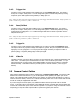
Frame Grabber Pin-out
Figure 5
Operator’s Manual LBA-PC
Doc. No. 10654-001, Rev 4.10
25