SIGMA MRX SERIES ANALOG AND DIGITAL MID-SIZE MATRIX ROUTING SYSTEM OPERATORS MANUAL SIGMA ELECTRONICS, INC. P.O.
UNPACKING PHYSICAL INSPECTION Inspect your packages and equipment for any damage that might have occurred during shipping. If damage has occurred, save the shipping cartons. Report the damage to the shipping company and notify Sigma Electronics, Inc. STANDARD SHIPPING CONFIGURATION Each MRX system will be shipped in multiple cartons. Video and Audio frames are shipped, each in their own carton, with all modules installed. Power supply frames and the required power supplies are shipped in the same carton.
SIGMA MRX SERIES ANALOG AND DIGITAL MID-SIZE MATRIX ROUTING SYSTEM OPERATOR’S MANUAL TABLE OF CONTENTS UNPACKING .......................................................................................................................................................................................i PHYSICAL INSPECTION ...............................................................................................................................................................i STANDARD SHIPPING CONFIGURATION..
INSTALLATION AND OVERVIEW GENERAL OPERATING REQUIREMENTS ENVIRONMENTAL Ambient temperature/Ventilation The MRX Switching System is designed to operate as specified when the ambient temperature is kept within the range of 0°C to 50°C. Ventilation slots are provided on the front and sides of the frames to assist in the removal of the excess heat generated in the normal operation of the units. These ventilation slots must not be blocked.
INTERCONNECT WIRING AUDIO FRAME - ANALOG The MRX Analog Audio Switching System is designed to accept both balanced and unbalanced audio signals having an input level of +26dBu or less in to Hi-Z (+24 dBu into 600Ω). Balanced audio signals are connected to the audio frame via a 3-wire cable attached to the 3-position, detachable, terminal block. Unbalanced signals can utilize a 2-wire conductor and connect the ground wire to both the “C” and ““ terminals on the 3-position, detachable, terminal block.
VIDEO FRAME - ANALOG Video signals are connected to the video frame via BNC jacks on the rear panel. Connect the source video cables to the corresponding input BNCs on the rear of the frame. The MRX routing switcher must be the terminating device in the system. All video modules provide the video source with proper 75Ω termination. All active video outputs must be terminated in 75Ω. (BNC’s for outputs that are beyond the configured matrix size do not need to be terminated.
To ensure that the SCI has power at all times, the control module is connected to every power module output. This guarantees that if any functional power supply module is installed, the SCI will have power supplied to it. In addition, as long as there is more than one operating power supply in the power frame, the SCI has redundant power capability. CONTROL BUS WIRING The data bus connection is provided on the rear of each power frame at the SCI interface panel.
REAR SUPPORTS Depending upon the installation, it may be necessary to install the included rear mounting frame supports. These supports are designed to allow connection to rear rails positioned between 19 and 30 inches from the front supports. To install, follow the directions below. Rear Support Installation Instructions Refer to illustration below for reference letters. 1.
CONTROL PANEL To initiate the switching operation, data must be input into the SCI. One way to input this data is through a control panel. The MRX system is capable of utilizing many different control panels available from Sigma Electronics, Inc. The data from the control panels is transferred to the SCI via a communication line. References to this line are typically abbreviated to COMM line.
APPENDICES
be either a composite video signal (1 Vp-p) or a composite sync pulse (-4vpp). The SCI will use this reference to determine the vertical interval switch. If no “REF IN” signal is present the SCI will execute the switch as soon as it is interpreted. APPENDIX A – SCI PROTOCOL AND INTERFACE INTRODUCTION SCI Configuration Switches The SCI serial interface card is the heart of the Sigma MRX Series mid-size matrix routing system.
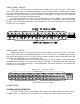
APPENDIX A – SCI PROTOCOL AND INTERFACE COMMAND: STATUS RS232 PROTOCOL COMMANDS Any OUTPUT’s status can be obtained by entering the following protocol sequence: The following commands may be issued from a computer/terminal keyboard or other similar communication control device. This protocol is supported by various control systems provided by other control system manufacturers. Standard ASCII characters are used to create the command strings.
APPENDIX A – SCI PROTOCOL AND INTERFACE COMMAND: MATRIX SETUP REQUEST The SCI will respond by sending a carriage return and linefeed to move the cursor on the screen to the beginning of the next line. The input/output matrix setup information of the system can be displayed. To do this, send the following command: The SCI always gives priority to commands over responses. All commands are executed before any responses are sent. This assures the fastest processing of a change request.
APPENDIX A – SCI PROTOCOL AND INTERFACE SPECIAL COMMANDS COMMAND: HALT DATA TRANSMIT There are several special commands available that should be used with care. The SCI supports the XON/XOFF protocol. This is a method, through software, of halting and resuming transmission of data. The XOFF is activated by holding the Control key and pressing 'S' (CTRL-S). This will halt data transmission.. Incoming commands are still executed during an XOFF. It is the responses generated by the SCI that are not sent.
APPENDIX A – SCI PROTOCOL AND INTERFACE COMMAND: STORE SALVO COMMAND: SALVO STATUS ALL Creating a transaction to be stored in a salvo is done exactly as a regular transaction except the salvo symbol is the leading character. The following example will store this transaction in salvo 2 (@): The status of a salvo can be examined by prefixing the status command with the salvo symbol. @A10C3O19 {RETURN/ENTER} The example provided is for salvo 1 (!). This example provides the status (S) for all outputs (A).
APPENDIX A – SCI PROTOCOL AND INTERFACE @ZB {RETURN/ENTER} COMMAND: EXECUTE PRESET SALVO The example above for salvo 2 (@) will erase (Z) all level 2 (B) entries for each output specified in the salvo. To execute a preset salvo, choose the salvo number/symbol of the preset salvo. $ {RETURN/ENTER} It is also possible to erase a level for a specific output within a salvo. The example above will execute salvo 4 ($), which was in the preset mode.
APPENDIX A – SCI PROTOCOL AND INTERFACE SERIAL CONTROL AND MODE SWITCHES The system configuration DIP switches S2 and S3 are located on the front edge of the SCI-MRX printed circuit board. The power supply frame holds the SCI-MRX module. Remove the front panel of the frame to access the switches. The momentary push-button reset switch S1 is positioned next to S3. See INTRODUCTION for details. This chart sets the communications Baud Rate.
APPENDIX A – SCI PROTOCOL AND INTERFACE JUMPER SELECTION SERIAL PORT COMMUNICATION FORMAT RS-232 SELECTION JP2, 9 position jumper with header attached, factory default. RS-422/485 SELECTION JP1, 9 position jumper, move header from JP2 to this position for RS-422/485.
APPENDIX A – SCI PROTOCOL AND INTERFACE 9 PIN 'D' RS-232 PIN ASSIGNMENT PIN # FUNCTION∗ DIRECTION 1 N/C ---- 2 RECEIVE DATA INPUT to SCI-MRX 3 TRANSMIT DATA OUTPUT from SCI-MRX 4 DATA TERMINAL READY OUTPUT from SCI-MRX 5 SIGNAL GROUND N/A 6 DATA SET READY INPUT to SCI-MRX 7 READY TO SEND OUTPUT from SCI-MRX 8 CLEAR TO SEND INPUT to SCI-MRX 9 N/C ---- The Pin assignments noted are per the RS-232 standard.
APPENDIX A – SCI PROTOCOL AND INTERFACE RS-232C WIRING SCI-MRX 9 PIN 'D' PIN SIGNAL DESIGNATION SERIAL PORT CONNECTIONS (COMM 1-DCE) SERIAL PORT CONNECTIONS (COMM 2-DTE) N/C 1- N/C N/C 2- RECEIVE DATA (RXD) [INPUT] RXD OR TXD 3- TRANSMIT DATA (TXD) [OUTPUT] TXD OR RXD 4- DATA TERMINAL READY (DTR) [OUTPUT] CTS CTS 5- SIGNAL GROUND GROUND GROUND 6- DATA SET READY (DSR) [INPUT] RTS RTS 7- READY TO SEND (RTS) [OUTPUT] DSR DSR 8- CLEAR TO SEND (CTS) [INPUT] DTR DTR 9- N/C
APPENDIX B - SPECIFICATIONS SYSTEM CONTROL INTERFACE MODULE (MRX-SCI) Data Transmission System ................................RS-232 & RS-422 Serial Port Baud Rate ........................................Up to 57.6 Kb baud Control Levels ....................................................Four or eight Communication Line ..........................................Coaxial, up to 2000 feet Control Panels ...................................................Up to 64 on 2 Comm. Lines Number of Salvos ............
APPENDIX B - SPECIFICATIONS DIGITAL VIDEO FRAME (MRX-DVF) Signal Type........................................................SMPTE 259M Connectors ........................................................75 Ohm BNC Inputs.................................................................32, single-ended, terminated, 800mV p-p Input return loss .................................................15 dB min. from 5 MHz to 270 MHz Equalization .......................................................
APPENDIX B - SPECIFICATIONS DIGITAL AUDIO FRAME – Unbalanced (MRX-CDAF) Signal Type........................................................AES-3id 1995 Connectors ........................................................75 Ohm BNC Inputs.................................................................32, single-ended, terminated, 1V p-p max. Input return loss .................................................15 dB min. from 0.1 MHz to 6.0 MHz Input impedance ................................................