
Operator`s manual


APPENDIX A – SCI PROTOCOL AND INTERFACE
A10
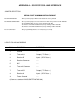
RS-232C WIRING
SCI-MRX 9 PIN 'D'
SERIAL PORT SERIAL PORT
PIN SIGNAL CONNECTIONS CONNECTIONS
DESIGNATION (COMM 1-DCE) (COMM 2-DTE)
1- N/C N/C N/C
2- RECEIVE DATA (RXD) [INPUT] RXD OR TXD
3- TRANSMIT DATA (TXD) [OUTPUT] TXD OR RXD
4- DATA TERMINAL READY (DTR) [OUTPUT] CTS CTS
5- SIGNAL GROUND GROUND GROUND
6- DATA SET READY (DSR) [INPUT] RTS RTS
7- READY TO SEND (RTS) [OUTPUT] DSR DSR
8- CLEAR TO SEND (CTS) [INPUT] DTR DTR
9- N/C N/C N/C
Although the RS-232C standard defines the use of 25 pins, only nine of those are needed for basic PC
serial communications. Of those nine, only seven are required for serial communications with the SCI-MRX.
The above wiring chart is typical for most IBM and compatible type PC's. However, it is always best to check
with the manufacturer's wiring specifications to determine exact pin assignments before beginning. This is
especially true if using COMM 1, since some manufacturers use a 9 pin 'D' connector instead of a 25 pin 'D'.
Regardless of the connector, the signal connections are the same. RXD and TXD are reversed depending
upon whether the serial port is configured as a DTE (data terminal equipment) or a DCE (data communications
equipment).
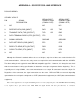
If the control equipment does not require handshaking, there is no need to jumper the pins on the SCI-MRX. When handshaking
is not required only 3 pins will be used: TXD, RXD and Signal Ground. All other pins will have no connection.