Operating and Maintenance Manual MAN-027-May 2007
DANGER - IMPORTANT WARNINGS The system must be operated only by trained and qualified radiographers who have read and understand this Operating Manual or by trained assistants working under their direct supervision. WARNING The use of this radiographic exposure device by unqualified personnel or when safety procedures are not fully met could result in life-threatening dangers. Gamma radiography systems emit high levels of highly penetrating radiation during use.
CONTENTS _______________________________________________________________________ 1 TECHNICAL SPECIFICATIONS 1.1 – 1.7 _______________________________________________________________________ 2 OPERATING INSTRUCTIONS 2.1 – 2.11 _______________________________________________________________________ 3 DAILY INSPECTION INSTRUCTIONS 3.1 – 3.9 _______________________________________________________________________ 4 MAINTENANCE INSTRUCTIONS 4.1 – 4.
880 Delta 150 Ci (5.55 TBq) Maximum package weight With jacket 52 lb (24 kg) Without jacket 46 lb (21 kg) 880 Sigma 130 Ci (4.81 TBq) Maximum package weight With jacket 52 lb (24 kg) Without jacket 46 lb (21 kg) 880 Elite 50 Ci (1.85 TBq) Maximum package weight With jacket 42 lb (19 kg) Without jacket 33 lb (17 kg) 880 Omega* 15 Ci (0.
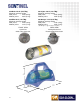
TECHNICAL SPECIFICATIONS Exposure Device Description The Model 880Delta, Model 880 Sigma, Model 880 Elite and Model 880 Omega are physically small, lightweight, portable industrial radiographic exposure devices. The ‘S’ tube design exposure device consists of a cast depleted Uranium (DU) shield contained and secured within a 300 series stainless steel tube with stainless steel discs welded at each end to form a cylinder shaped housing.
TECHNICAL SPECIFICATIONS Applications The Model 880 devices are used for industrial applications of gamma radiography, mainly with Iridium192, to inspect materials and structures in the density range of approximately 2.71 g/cm3 through 8.53 g/cm3. The Model 880 devices also accommodate low energy isotopes to permit radiography of materials and structures of thin sections of steel and low-density alloys.
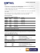
TECHNICAL SPECIFICATIONS Model 880 Elite authorized contents Isotope Assembly Model Number Gamma Energy Range Half Life Ytterbium-169 Selenium-75 Iridium-192 Cobalt-60 Cesium-137 91810 A424-25W A424-9 A424-19 A424-30 8-308 keV 66-401 keV 206-612 keV 1.17-1.33 MeV 663 keV 32 days 120 days 74 days 5.27 years 30 years Approximate Steel Working Thickness 2-20 mm 3-29 mm 12-63 mm 50-150 mm 12-63 mm Device/Source Maximum Capacity 20 Ci 0.74 TBq 150 Ci 5.55 TBq 50 Ci 4.81 TBq 25 mCi 925 MBq 380 mCi 14.
TECHNICAL SPECIFICATIONS Note: The total length of source guide tubes utilized must be shorter in length than the remote controls to ensure the source assembly will project into the working position. e.g. When using 25 ft (7.6 m) remote controls, a maximum of three 7 ft (2.1 m) source guide tubes can be used with a combined length of 21 ft (6.4 m). Conversely, when using 35 ft (10.7 m) remote controls, a maximum of four 7 ft (2.1 m) source guide tubes can be utilized.
TECHNICAL SPECIFICATIONS Exposure Device Specifications Manufacturer Length Sentinel - QSA Global, Inc. 40 North Avenue, Burlington, Massachusetts, USA 01803 13.33 in (33.8 cm) all models Primary Application Width Industrial gamma radiography 7.5 in (19.1 cm) all models Model Numbers Height Model 880 Delta, Model 880 Sigma, Model 880 Elite and Model 880 Omega 9 in (22.
TECHNICAL SPECIFICATIONS Construction A depleted Uranium (DU) shield is encased within a welded tubular stainless steel shell with stainless steel end plates. The interior void space is filled with rigid polyurethane foam. The exposure device body is encased in an engineered plastic jacket also consisting of the handle and a base. Materials Titanium ‘S’ tube, DU shield, 300 series stainless steel tubular shell and plate, aluminum, brass, tungsten and polyurethane.
TECHNICAL SPECIFICATIONS Warranty and Limitation of Liability QSA Global, Inc. (herein referred to as the manufacturer) warrants its product which it manufactures and sells to be free from defects in material and workmanship for a period of one year from the date of shipment. This warranty shall not apply to any product or parts which have been subjected to misuse, improper installation, repair, alteration, neglect, accident, abnormal conditions of operation, or use in any manner contrary to instructions.
OPERATING INSTRUCTIONS Job site safety precautions Instruments The radiographer and radiography assistants must at all times wear a film badge or TLD and pocket dosimeter with a range of 0-2 mSv (0-200 mRem). Regulatory requirements in the USA also require that an audible alarm ratemeter be worn at temporary jobsites. Specifically, those locations that are not permanent radiographic installations equipped with functional door interlocks and audible/visual alarms.
OPERATING INSTRUCTIONS It is essential that the 5 STEPS set out below are followed in the correct order to ensure safe operation and compliance with regulations. STEP 1 Exposure Device Survey STEP 2 Connecting the Source Guide Tube(s) STEP 3 Connecting the Remote Control Cable STEP 4 Projecting and Retracting the Source Assembly STEP 5 Dismantling Equipment STEP 1 Exposure Device Survey Check the operation of the survey meter by measuring the radiation level at the surface of the exposure device.
OPERATING INSTRUCTIONS STEP 2 Connecting the Source Guide Tube(s) 1 Simultaneously pull and rotate the spring-loaded outlet port cover a quarter of a turn in a clockwise direction. 2 Insert the bayonet fitting of the source guide tube Into the exposed outlet port. Align the GREEN MARKINGS on the bayonet fitting and outlet port. 3 Rotate a quarter of a turn counter-clockwise. 4 Rotate the spring-loaded outlet port cover an additional 60 degrees in a clockwise direction until it stops. 2.
OPERATING INSTRUCTIONS STEP 2 WARNING Ensure that the available length of the control cable is greater than the total length of the source guide tubes. See the technical specifications section for details. If the remote control conduits are shorter than the total length of the source guide tubes: 1 The source assembly cannot be projected all the way to the source stop of the terminating source guide tube and be correctly positioned for the exposure.
OPERATING INSTRUCTIONS STEP 3 Connecting the Remote Control Cable 1 2 3 Unlock the plunger lock with the key. Turn the selector ring from LOCK to CONNECT The protective cover will disengage from the projector. 2.
OPERATING INSTRUCTIONS STEP 3 Connecting the Remote Control Cable 4 Insert the protective cover into the lock housing during use of the device. Check the control cable and source assembly connectors using the NO GO gauge according to the daily inspection section. 5 Remove the protective rubber cap from the remote control connector.
OPERATING INSTRUCTIONS STEP 3 Connecting the Remote Control Cable 8 Close the jaws of the control cable connector over the joined connectors. Slide the remote control connector assembly collar over the connector jaws. NOTE: The control cable connector, when properly installed with the selector ring in the CONNECT position, displaces antirotation lugs which allows the selector ring to be rotated to the LOCK position and when required, through to the OPERATE position.
OPERATING INSTRUCTIONS STEP 4 Projecting and Retracting the Source Assembly 1 Unlocking If engaged, unlock the exposure device’s plunger lock with the key. 2 Rotate the selector ring to the OPERATE position. Ensure there is no tension/force in either direction on the control cable.
OPERATING INSTRUCTIONS STEP 4 Projecting Rapidly rotate the control crank handle in the EXPOSE direction (counter-clockwise) to move the source assembly out of the exposure device to the radiographic focal position. The control crank handle will stop turning when the source reaches the source stop. Do not use excessive force. The odometer (if fitted) will indicate the approximate total distance traveled, 7 ft (2.1 m) for each guide tube section.
OPERATING INSTRUCTIONS STEP 4 Retracting At the end of the required exposure time, set the brake to OFF and rapidly turn the crank handle in the RETRACT (clockwise) direction until it no longer moves. You may hear the lock slide ‘click’ back into its original position depending on the ambient noise level at the job site. From the control crank you may be able to observe the GREEN MARKING on the slide bar.
OPERATING INSTRUCTIONS STEP 5 Dismantling equipment Remote control unit Unlock the exposure device and then rotate the selector ring counter-clockwise from LOCK to CONNECT. The remote control connector will partially disengage from the exposure device's locking mechanism. Completely disengage the remote controls from the exposure device by disengaging the control cable connector from the source assembly connector.
DAILY INSPECTION INSTRUCTIONS Introduction The QSA Global, Inc. Model 880 Delta, Sigma, Elite and Omega radiographic exposure devices provide innovation to the most widely used family of radiographic exposure devices utilized for on-site gamma radiography. The Model 880 Series exposure devices are portable, lightweight and permit use of several different isotopes commonly needed by the nondestructive testing community.
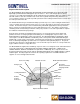
DAILY INSPECTION INSTRUCTIONS Figure 3.1 Source assembly and remote control cable connectors 2 Exposure Device The source assembly is shown in the stored position in a titanium or ‘S’ tube at the center of the depleted Uranium shield of the exposure device. (See figure 3.2) A remote control unit is shown with its control cable connector coupled to the source assembly. High density depleted Uranium shielding is used in the exposure device to provide good radiological protection with minimal weight.
DAILY INSPECTION INSTRUCTIONS First, the locking mechanism requires a deliberate action to enable exposure of the source assembly. This is accomplished by coupling the control cable connector to the source assembly connector, coupling the remote control connector to the exposure device locking mechanism and then pushing a lock slide from the SECURED position into the EXPOSE position.
DAILY INSPECTION INSTRUCTIONS Transit Mode Rotating the handle of the remote control crank in the EXPOSE direction (counter-clockwise) moves the source assembly out of the shielded position in the exposure device and into the source guide tubes (projection sheaths). (See figure 3.3) The source assembly is under positive mechanical control using the remote control crank. The remote controls may be fitted with an odometer to provide an indication of the sealed source’s position.
DAILY INSPECTION INSTRUCTIONS Source Assembly Control Cable Remote Control Crank Exposure Device Locking Mechanism Sealed Source Shield Outlet Port Source Guide Tubes Figure 3.4 Sealed source in the exposure mode Daily Inspection of the System A daily inspection of the gamma radiography system for obvious defects is essential to ensure the equipment is in a safe and proper operating condition.
DAILY INSPECTION INSTRUCTIONS 2 Inspect the labels on the exposure device or the transport case to ensure they are legible and securely attached to the unit. The warning label containing the trefoil should be legible from a distance of at least 3 ft (approximately 1 m). This label warns the individuals in the immediate vicinity of the presence of radioactive materials and permits them to take measures to minimize their exposure to radiation. The printed verbiage and the radiation symbol must be legible.
DAILY INSPECTION INSTRUCTIONS odometers to obtain an approximation of the travel distance. One full revolution of the crank handle is equal to approximately 10 in (25.4 cm) of travel. Two remote control conduits (sheaths, housings) are attached to the control crank. One conduit contains the working side of the control cable that drives the source assembly out of the exposure device and through the source guide tubes.
DAILY INSPECTION INSTRUCTIONS 2 Control Conduit Inspection: a. Inspect the control conduit where it is swaged onto the fittings that mount on the control crank. There should be no evidence of cracks or breaks in the PVC sheath. Also, look for bulges in that area that result from repeated flexing. b. Visually inspect the entire length of both control conduits looking for dents, cuts and thermally damaged areas. During this inspection, the radiographer should use his hands to feel for inward dents.
DAILY INSPECTION INSTRUCTIONS d. A final check of the control cable connector and source assembly connector is accomplished by use of a Model 550 NO GO gauge to check for significant wear on the connectors that would affect safety. Without using excessive force, check the following four positions (see figure 3.5): 1 Ball at the end of the control cable connector must NOT GO into the hole of the gauge.
MAINTENANCE INSTRUCTIONS Quarterly (Routine) and Annual (Complete) Maintenance Requirements Radiographic exposure devices and associated equipment must be maintained regularly by trained and qualified personnel to ensure consistent and safe operation of the radiographic system.
MAINTENANCE INSTRUCTIONS Routine (Quarterly) Maintenance Requirements 1 Remote Controls Disassemble, clean, inspect and maintain the remote control crank, control conduits and control cable according to the complete service section. Record the results of the inspection and any repairs that are performed. Any components found to be deficient during the inspection must be removed from service until repaired or replaced. Deficient components must be labeled with a status indicator to prevent inadvertent use.
MAINTENANCE INSTRUCTIONS f. Check the locking mechanism and plunger lock to verify attachment and operation. Grasp the entire mechanism with one hand and attempt to shift the mechanism. Retaining screws that have been loosened from excessive vibration or improper maintenance will allow the movement of the locking mechanism during this check. Loose screws must be tightened according to the annual maintenance requirements prior to use or transport. g.
MAINTENANCE INSTRUCTIONS Routine (Quarterly) Maintenance Records Records of all equipment inspected and maintained during the routine maintenance must be recorded. Records should indicate: • • • • • • The date of inspection and maintenance. Name and signature of the qualified individual performing the required inspections. Problems found and maintenance or repairs performed. Model number and serial number of the exposure device and transport container.
MAINTENANCE INSTRUCTIONS Leak Testing Leak Test of the Radioactive Sealed Source Periodic leak tests of the radioactive sealed source are required by most national and international regulations. The leak test provides a confirmation of the integrity of the hermetically welded sealed source by determining the amount of removable contamination. In most regulatory jurisdictions, a leak test of a sealed source must be performed every 6 months or prior to its first use after removal from storage.
MAINTENANCE INSTRUCTIONS The analysis performed on the wipe test must be capable of detecting the presence of 0.005 µCi (185 Bq) of radioactive material on the test sample. If the test sample reveals 185 Bq (0.005 µCi ) or more of removable DU contamination, the exposure device must be removed from service until an evaluation of the wear on the ‘S’ tube has been made. Should the evaluation reveal that the source tube is worn through, the exposure device may not be used again.
MAINTENANCE INSTRUCTIONS Model 880 Series Annual Maintenance Requirements Model 880 Series exposure devices must receive inspection and maintenance at least once a year. The locking mechanism and outlet port mechanism must be removed from the exposure device and disassembled for proper cleaning, inspection and lubrication of components that are critical to safety.
MAINTENANCE INSTRUCTIONS 5 Begin assembly of the locking mechanism by lightly coating all components with MIL-G-23827B (or C), MIL-PRF-23827C, (or equivalent radiation resistant grease authorized by QSA Global, Inc.). Treat all screw thread ends with Vibratite™ or Locktite™ thread sealant. Mount the locking mechanism plate horizontally in a vise or fixture with the plunger lock and retainer at a 12 o’clock position.
MAINTENANCE INSTRUCTIONS 7 Remove the front plate containing the outlet port mechanism from the empty Model 880 device by removing the four 5/16-18 x 1½ in socket button-head screws using the tamperproof tool bit mounted in a ratchet. After removing the outlet port mechanism, clean the ‘S’ tube of the exposure device by pushing cloth swabs wetted with solvent through the ‘S’ tube until they come out clean. Use a dry cloth swab to remove any residual solvent from the ‘S’ tube after cleaning.
MAINTENANCE INSTRUCTIONS 8 Re-assemble the Model 880 exposure device by performing the following steps: Apply PermantexTM anti-seize thread lubricant to the first several end threads of the back plate’s (locking mechanism) four 5/16-18 x 1½ in socket button-head screws. Align and attach the locking mechanism assembly to the exposure device’s end plate by installing the four 5/16-18 x 1½ in screws using a tamperproof tool bit mounted in a calibrated torque wrench.
MAINTENANCE INSTRUCTIONS Annual Maintenance for the Remote Controls Tools required for complete maintenance of Models 692, 693, 664 remote controls: • • • • • • • • • 11/16 in open-end wrench for the control conduit swage fittings. 1/2 in open-end wrench for the 5/16 in control crank handle bolt. Slot screwdriver for the 10-32 remote control crank screws. 3/8 in wrench for the 10-32 control crank stop nuts. 0.
MAINTENANCE INSTRUCTIONS 7 Perform the following inspections of the control cable: a. Use the Model 550 NO GO gauge to inspect the control cable connector for wear. Closely inspect the connector for bends or cracks in the neck (shank) area and dented areas on the ball of the connector. Remove the control cable from service if any cracks or bends in the shank or dents in the ball of the male connector are found during this inspection.
MAINTENANCE INSTRUCTIONS Clean the interior of both remote control conduits by pouring 4-5 oz (100 ml) of clean solvent into one end. Use compressed air to blow the solvent through the entire length of conduits into a clean white cloth attached to the opposite end. Repeat this cleaning process until the solvent blown through the conduit comes out clean. Use the compressed air to thoroughly dry the interior of the conduit.
MAINTENANCE INSTRUCTIONS CAUTION Wear safety glasses when inserting the wear strip. It will be under tension and could suddenly fly out during assembly. Place the drive wheel in the lower half of the control crank housing making sure the spacer rings are between it and the wheel bearings if applicable. Assemble the two brake jaws, brake bearing and brake arm. The angled sides of the brake jaws should be facing the retract side of the control crank housing.
MAINTENANCE INSTRUCTIONS Connect the RETRACT control housing to the control crank housing. Retract the control cable fully, watching for any binding that may indicate damage to the control housing. If applicable, reset the odometer to zero with the control cable fully retracted. Replace the protective rubber cap over the end of the safety connector assembly.
MAINTENANCE INSTRUCTIONS 4 Inspect the swage fittings of each source guide tube to ensure the threads are not stripped or galled. If the threads are damaged, the use of a 1in-18 tap or die and oil can be used to clean the damaged area. Using moderate pressure, attempt to twist the swage fitting off the source guide tube. If any movement is possible, remove from service and replace the swage fitting.
MAINTENANCE INSTRUCTIONS Annual Maintenance Records Records of all equipment inspected and maintained during the annual maintenance must be recorded. Records should indicate: • • • • • • the date of the inspection and maintenance. name of the qualified individual performing the required inspections. problems found and maintenance or repairs performed. model number and serial number of the exposure device. associated equipment that was inspected and maintained.
MAINTENANCE INSTRUCTIONS Rear Plate Assembly 4.
MAINTENANCE INSTRUCTIONS REAR PLATE ASSEMBLY ITEM 1 2 3 4 5 6 7 8 9 10 PART NO. 88014 85701-5 88026 SPR005 88025 88024 SPR006 66001-6 SPR004 88021 QTY. 1 1 1 1 1 1 1 2 2 1 DESCRIPTION LOCK COVER ASSEMBLY SELECTOR RING RETAINER SELECTOR RING COMPRESSION SPRING SLEEVE LOCK SLIDE COMPRESSION SPRING ANTI-ROTATE LUGS COMPRESSION SPRING REAR PLATE ITEM 11 12 13 14 15 16 17 18 19 20 PART NO. SCR003 SCR072 SLV005 88022 66001-11 SCR023 66001-811 66001-20 QTY.
MAINTENANCE INSTRUCTIONS Front Plate Assembly 4.
MAINTENANCE INSTRUCTIONS FRONT PLATE ASSEMBLY ITEM 1 • 2 • 3 4 5 • 6 7 • PART NO. 88033 88033A SCR162 PIN036 88031 88036 88032 88032A SPR033 88037 88037A QTY. 1 1 1 1 1 2 1 1 2 1 1 DESCRIPTION PORT COVER (SET SCREW TYPE) PORT COVER (ROLL PIN TYPE) SET SCREW ROLL PIN FRONT PLATE WASHER ROTOR (ROLL PIN TYPE) ROTOR (SET SCREW TYPE) COMPRESSION SPRING SHAFT (SET SCREW TYPE) SHAFT (ROLL PIN TYPE) ITEM 8 9 10 11 • 12 • 13 • PART NO. PIN024 SCR160 88039 88034 88034A PIN038 SCR157 88035 QTY.
MAINTENANCE INSTRUCTIONS CONTROL ASSEMBLIES SOURCE GUIDE TUBES 4.
MAINTENANCE INSTRUCTIONS CONTROL ASSEMBLIES ITEM 1 2 3 4 5 6 PART NO. SCR125 SCR008 BLT008 WSH019 68901 BBS-004 QTY.
MAINTENANCE INSTRUCTIONS 28 2 22 29 22 26 27 1 4.
SAMPLE TRANSPORTATION INSTRUCTIONS The following instructions are samples for the transport of this radiographic exposure device/transport container and source assembly within the United States and are based on current transport regulations. Shippers of radioactive materials in regulatory jurisdictions outside the USA must ensure full compliance with all current and applicable transport regulations.
SAMPLE TRANSPORTATION INSTRUCTIONS Receipt of Radioactive Material NOTE 1 A radioactive material package must be accepted from the carrier at the time it is delivered. [10CFR20.1906(a)(1)] 2 If a radioactive material package is to be held at the carrier's terminal for pickup, arrangements must be made to receive notification from the carrier of the arrival of the package at the time of arrival. The package must be picked up expeditiously upon receipt of notification (within three hours if practicable).
SAMPLE TRANSPORTATION INSTRUCTIONS Shipment of Radioactive Material 1 Prior to shipment of a Type B package within the USA, assure that you are a registered user of the radioactive material package you wish to ship. Also, assure that you have appropriate quality assurance procedures for Type B packages. [10CFR71.12, 10CFR34.
SAMPLE TRANSPORTATION INSTRUCTIONS 6 If the shipping package is to be packaged inside a crate or other outer packaging, the outer packaging must be strong enough to withstand the normal conditions of transport and must not reduce the safety of the package. The shipping package must be placed within the outer package with sufficient blocking to prevent shifting during transportation. [49CFR173.
SAMPLE TRANSPORTATION INSTRUCTIONS The TI is the maximum radiation level measured in mRem/hr at a distance of 1m from the external surfaces of the package. When recording the TI, the dose rate units of mRem/hr are not listed, for example a reading of 20 µSv/hr (2 mem/hr) would indicate a TI = 2.0. (Note that the TI is rounded to the nearest tenth value.) 8 Properly complete two shipping labels indicating the contents (e.g. Ir-192), the activity of the source (in Becquerels or multiples of Becquerels, e.g.
SAMPLE TRANSPORTATION INSTRUCTIONS NOTE: For shipments in company vehicles to and from job sites, the shipper’s certification is not required. k. The shipping papers must indicate your company's emergency telephone number. The telephone number must have 24-hour coverage in case of an emergency concerning your shipment. The telephone number must be clearly visible on the shipping paper and must be answered by a person that can provide immediate emergency response information.
SAMPLE TRANSPORTATION INSTRUCTIONS Shipment of Empty Uranium Shielded Containers 1 Assure that the package does not contain a radioactive source. Perform the following procedure to confirm there are no unauthorized source assemblies within the container: • • • • • • Transfer the authorized source assembly from the exposure device in accordance with the source changer operations manual.
SAMPLE TRANSPORTATION INSTRUCTIONS ii. 6 Required after 1 January 2007, the outside of the package must include the following label [IATA 10.7.4.4.3]: If the surface radiation level exceeds 5 µSv/hr (0.5 mRem/hr), or if there is a measurable radiation level at 1m from the surface, use the criteria of Table 1 to determine the proper shipping labels to be applied to the package. a.
SAMPLE TRANSPORTATION INSTRUCTIONS ix. For air shipments, the package must be labeled with a ‘Cargo aircraft only’ label and the shipping papers must state: ‘This shipment is within the limitations prescribed for cargo only aircraft’. x. Your company's 24-hour emergency telephone number. xi. The weight of the package including the unit of measurement of the hazardous material covered by the description (e.g. 100 lb). (Note: For air shipments, the weight must be in multiples of kilograms.) c.
SAMPLE TRANSPORTATION INSTRUCTIONS 3 Place the transport package in the vehicle. Properly brace and secure the package against movement in the vehicle. [49CFR177.842(d)] 4 Survey the driver's compartment to assure that the radiation level does not exceed 0.02 mSv/hr (2 mRem/hr). [49CFR177.842(g)] Note: This requirement is mandatory only for exclusive use shipments by a common carrier. [49CFR173.
SAMPLE TRANSPORTATION INSTRUCTIONS Radioactive material transport checklist Date Operator Destination Transport Container Model Serial Number Radionuclide Activity Type of Label Applied Transport Index Survey Meter Model Serial Number Calibration Date Film Badge Dosimeter Serial Number Initial Reading Final Reading Radiation Area Signs Packing List Rope Bill of Lading Radioactive Material Sign Emergency Equipment Radiation Survey Driver’s Compartment (Record highest reading) Vehicle
DEFINITIONS AND TERMS Area alarm An area radiation level monitor that provides a highly visual warning when the radiation level exceeds a pre-set threshold. Commonly referred to as Gammalarms, use is required by most jurisdictions in permanent radiographic installations and they are often used in conjunction with door interlocks and audible alarms. Portable area alarms are required by some jurisdictions for radiography performed at temporary job-sites.
DEFINITIONS AND TERMS Exposure head Device which locates the sealed source included in the source assembly, in the selected working position and prevents the source assembly from projecting out of the projection sheath. Also known as: source stop, end stop, snout and head-hose. Locked position Describes the condition when the lock on a radiographic exposure device or transport container is fully engaged to lock the source assembly in place and the key is removed from the lock.
DEFINITIONS AND TERMS Source assembly A source holder with a sealed source attached or included. In cases where the sealed source is directly attached to the control cable without the use of a source holder, the source assembly is the control cable with the sealed source attached. In cases where the sealed source is not attached to the control cable nor included within the source holder, the sealed source is the source assembly.
EMERGENCIES AND PERSONNEL SAFETY Emergencies During the termination of a radiographic exposure, observation of the survey meter provides an indication of source movement while cranking the remote control handle. After retracting the sealed source into the exposure device, radiographers are required to perform a confirmatory survey of the exposure device, the projection sheaths and beam limiter when used.
EMERGENCIES AND PERSONNEL SAFETY Access to Restricted Areas The site where radiography is performed must be separated from other work areas by as much distance as possible. If applicable, check for occupation of the areas above and below the radiography site. Clearly defined boundaries must be set up and warning signs displayed to provide warning and prevent access to the radiography site by unauthorized personnel before any exposure begins.
INSTRUCTIONS FOR DISPOSAL Disposal By international regulations, radioactive materials that are no longer required must be transferred to a licensed recipient for final disposition. Cobalt-60 source assemblies that have depleted beyond their useful working life may be returned to authorized recipients using a source changer authorized for the specific model source assembly. Authorized recipients will provide any specific conditions to the shipper as required by regulatory authorities.
Sales SENTINEL™ QSA Global, Inc. 6765 Langley Drive Baton Rouge, Louisiana 70809 USA Telephone + 1 225 751 5893 Toll Free + 1 800 225 1383 Fax + 1 225 756 0365 or + 1 225 751 8082 Manufacturing SENTINEL™ QSA Global, Inc. 40 North Avenue, Burlington, Massachusetts 01803 USA Telephone + 1 781 272 2000 Toll Free + 1 800 815 1383 Fax + 1 781 273 2216 Email: Website: sales@sentinelndt.com www.sentinelndt.com abc All goods and services are sold subject to the terms and conditions of QSA Global, Inc.