Operating instructions Diaphragm Motor-Driven Metering Pump Sigma / 2 Basic Type S2Ba P_SI_0074_SW Please carefully read these operating instructions before use! · Do not discard! The operator shall be liable for any damage caused by installation or operating errors! Technical changes reserved. Part no.
Supplemental instructions Supplementary information Read the following supplementary information in its entirety! Should you already know this information, you will benefit more from referring to the operating instructions. The following are highlighted separately in the document: Fig.
Table of contents Table of contents 1 Identity code.................................................................................... 4 2 Safety chapter................................................................................. 6 3 Storage, transport and unpacking................................................. 11 4 Overview of equipment and control elements............................... 12 5 Functional description.................................................................... 14 5.
Identity code 1 Identity code S2Ba Sigma 2 Basic Type H Main power end, diaphragm Type: Capacity ____ __ Performance data at maximum back pressure and type: see nameplate on pump housing Dosing head material PV PVDF SS Stainless steel Seal material T PTFE seal Displacement body S Multi-layer safety diaphragm with optical rupture indicator A Multi-layer safety diaphragm with diaphragm rupture signalling (contact) H Diaphragm for hygienic pump head Dosing head design 0 no valve springs 1 wi
Identity code S2Ba Sigma 2 Basic Type _ Connection data - refer to nameplate on motor 1 No motor, with B14 flange, size 71 (DIN) 2 No motor, with C 42 flange (NEMA) 3 No motor, with B 5, size 56 (DIN) Degree of protection 0 IP 55 (standard) 1 Exe design ATEX-T3 2 Exd version ATEX-T4 Stroke sensor 0 No stroke sensor (standard) 2 Pacing relay (reed relay) 3 Stroke sensor (Namur) for haz‐ ardous locations Stroke length adjustment 0 Manual (standard) 1 With servomotor, 230 V, 50/60 Hz 2 Wi
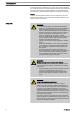
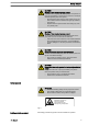
Safety chapter 2 Safety chapter CAUTION! These operating instructions include notes and quotes from German guidelines relating to the system operator's scope of responsibility. This information does not discharge the oper‐ ator from his responsibility as an operator and is intended only to remind him or make him aware of specific problem areas. This information does not lay claim to being complete, nor applicable to every country and every type of application, nor to being unconditionally up-to-date.
Safety chapter n n n n n n n n n Qualification of personnel Observe the general limitations with regard to viscosity limits, chem‐ ical resistance and density - see also ProMinent Resistance List (in the Product Catalogue or at www.prominent.com/en/downloads)! All other uses or modifications are prohibited.
Safety chapter An instructed person is deemed to be a person who has been instructed and, if required, trained in the tasks assigned to him/her and possible dan‐ gers that could result from improper behaviour, as well as having been instructed in the required protective equipment and protective measures. Service Customer Service department refers to service technicians, who have received proven training and have been authorised by ProMinent or Pro‐ Maqua to work on the system.
Safety chapter CAUTION! Warning of feed chemical spraying around Feed chemical can spray out of the hydraulic components if they are manipulated or opened due to pressure in the liquid end and adjacent parts of the system. – – Disconnect the pump from the mains power supply and ensure that it cannot be switched on again by unauthor‐ ised persons. Depressurise the system before commencing any work on hydraulic parts.
Safety chapter n n n Drive front cover Motor fan cowling Terminal box cover, motor Only remove them when the operating instructions request you to do so. Information in the event of an emergency In the event of an electrical accident, disconnect the mains cable from the mains or press the emergency cut-off switch fitted on the side of the system! If feed chemical escapes, also depressurise the hydraulic system around the pump as necessary. Adhere to the safety data sheet for the feed chemical.
Storage, transport and unpacking 3 Storage, transport and unpacking Safety notes WARNING! Only return the metering pump for repair in a cleaned state and with a flushed liquid end - refer to the chapter "Decom‐ missioning"! Only return metering pumps with a completed Decontamina‐ tion Declaration form. The Decontamination Declaration con‐ stitutes an integral part of an inspection / repair order.
Overview of equipment and control elements 4 Overview of equipment and control elements 1 2 4 3 5 P_SI_0068_SW Fig. 3: Overview of equipment and control elements S2Ba 1 2 3 4 5 Drive motor Drive unit Stroke length adjustment knob Liquid end with relief valve Diaphragm rupture sensor 1 2 P_SI_0088_SW Fig.
Overview of equipment and control elements 75% 0 50 25 75 20 30% 0 0 25 5 5 0 10 P_SI_0095_SW Fig. 5: Adjusting the stroke length n n n 100 % = 4 rotations 25 % = 1 rotation 0.5 % = 1 scale mark on stroke adjustment dial PG9 PG11 1 2 3 P_SI_0036 A B Fig.
Functional description 5 Functional description 5.1 Pump The metering pump is an oscillating diaphragm pump, the stroke length of which is adjustable. An electric motor drives the pump. 5.2 Liquid end The diaphragm (2) hermetically shuts off the pump volume of the dosing head (4) towards the outside. The suction valve (1) closes as soon as the diaphragm (2) is moved in to the dosing head (4) and the feed chemical flows through the discharge valve (3) out of the dosing head.
Functional description 1 2 3 4 5 P_SI_0019 Fig. 8: Integral relief valve 1 2 3 4 5 Spring, large Ball Rotary dial Spring, small Hose connection 5.4 Multi-layer safety diaphragm With visual diaphragm rupture sensors, in the event of a diaphragm rup‐ ture, the lowered red cylinder (6) springs forward beneath the transparent cover (7) so that it then becomes clearly visible - see Fig. 9. With the electrical diaphragm rupture sensor, a switch is switched.
Assembly 6 Assembly Compare the dimensions on the dimension sheet and pump. Base WARNING! Danger of electric shock If water or other electrically conducting liquids penetrate into the drive housing, in any other manner than via the pump's suction connection, an electric shock may occur. – h Position the pump so that it cannot be flooded. P_MOZ_0016_SW Fig. 10 WARNING! The pump can break through the base or slide off it – Ensure that the base is horizontal, smooth and perma‐ nently load-bearing.
Assembly Liquid end alignment Capacity too low The liquid end valves cannot close correctly if they are not upright. – Ensure that the discharge valve is upright. Fastening Capacity too low Vibrations can disrupt the liquid end valves. – m DN Secure the metering pump so that no vibrations can occur. Take the dimensions (m) for the fastening holes from the appropriate dimensional drawings or data sheets. Fix the pump base to the base with suitable screws. m P_MOZ_0015_SW Fig.
Installation, hydraulic 7 Installation, hydraulic WARNING! EX pumps in areas at risk from explosion – It is essential that metering pumps to be used in areas at risk from explosion are fitted with an appropriate safety relief valve on the outlet side of the metering pump (to protect it from excessive heating up from overloading and from impact sparks resulting from overloading trig‐ gered by the breakage of drive parts).
Installation, hydraulic CAUTION! Warning of feed chemical spraying around PTFE seals, which have already been used / compressed, can no longer reliably seal a hydraulic connection. – New, unused PTFE seals must always be used. CAUTION! Suction problems possible The valves may no longer close properly with feed chemicals with a particle size of greater than 0.3 mm. – Install a suitable filter in the suction line. CAUTION! Warning against the discharge line bursting With a closed discharge line (e.g.
Installation, hydraulic CAUTION! Warning of backflow Liquid ends, foot valves, back pressure valves, relief valves or spring-loaded injection valves do not constitute absolutely leak-tight sealing elements. P_SI_0022 – Use a shut-off valve, a solenoid valve or a vacuum breaker for this purpose. Fig. 15: Elastomer flat seal for a smooth insert Integral relief valve WARNING! Product can be dangerously contaminated Only with the design "Physiologically safety with regard to wetted materials".
Installation, hydraulic CAUTION! Danger of the integral relief valve failing The integral relief valve no longer operates reliably with feed chemicals having a viscosity of greater than 200 mPa s. – Only use the integral relief valve with feed chemicals having a viscosity up to 200 mPa s.
Installation, hydraulic 7.1 Basic installation notes Safety notes CAUTION! Danger resulting from rupturing hydraulic components Hydraulic components can rupture if the maximum permis‐ sible operating pressure is exceeded. – – Never allow the metering pump to run against a closed shut-off device. With metering pumps without integral relief valve: Install a relief valve in the discharge line.
Installation, electrical 8 Installation, electrical WARNING! EX pumps in areas at risk from explosion – Potential-free switches can be evaluated as simple elec‐ trical devices (EN 60079-14 or EN 50020). – Only connect potential-free as well as non-isolating low voltage switch accessories, such as diaphragm rupture indicators, stroke frequency instruments etc., to an intrinsically safe power circuit in areas at risk from explo‐ sion.
Installation, electrical WARNING! Danger of electric shock A mains voltage may exist inside the motor or electrical ancil‐ laries. – If the housing of the motor or electrical ancillaries has been damaged, you must disconnect it from the mains immediately. The pump must only be returned to service after an authorised repair.
Installation, electrical 1. Install a motor protection switch, as the motors have no fuse. 2. Install an emergency cut-off switch or include the motor in the emer‐ gency cut-off management plan for the system. 3. Only connect the motor to the voltage supply using a suitable cable. – – Key motor data can be found on the nameplate. The terminal wiring diagram is located in the terminal box.
Installation, electrical CAUTION! Danger resulting from unnoticed diaphragm rupture If the pump has been ordered with an electric diaphragm rup‐ ture sensor, it must also be electrically installed. – Install the enclosed diaphragm rupture sensor electri‐ cally to a suitable monitoring device. a) Diaphragm rupture sensor with switch contact – The cable can be poled as required.
Installation, electrical * at rated load The contacts are potential-free. The pacing relay is a N/O as standard. Supply voltage for pacing relay PCB Available supply vol‐ tages Mains supply fre‐ quency Power consumption 230 V AC (180-254 V) 50 / 60 Hz 10 mA (at 230 V, 50 Hz) 115 V AC (90-134 V) 50 / 60 Hz 15 mA (at 115 V, 60 Hz) 24 V DC (20-28 V) - 10 mA (at 24 V DC) Heating cartridge Install the heating cartridge according to its documentation.
Start up 9 Start up Safety notes WARNING! EX pumps in areas at risk from explosion – An appropriately skilled operative should check whether the appropriate installation information from the "Installa‐ tion " chapter has been implemented correctly. WARNING! Fire hazard with flammable media Only with combustible media: These may start to burn when combined with oxygen. – During filling and draining of the liquid end, an expert must ensure that feed chemical does not come into con‐ tact with oxygen.
Start up CAUTION! Possible environmental and material damage In event the red gear bleeding plug is sealed, during opera‐ tion it prevents any pressure compensation between the drive housing and the surroundings. This ensure that oil can be pushed from the drive housing. – Remove the gear bleeding plug before commissioning. Remove the gearbox vent stopper Before start up pull the red gearbox vent stopper off, see chapter "Over‐ view of equipment and control elements".
Start up When operating the integral relief valve close to the opening pressure, a minimal overflow into the overflow line can occur. Adjusting the stroke length Only adjust the stroke length when the pump is running. This is easier and also better for the pump. 75% 0 50 25 75 20 30% 0 0 25 5 0 5 10 P_SI_0095_SW Fig. 19: Adjusting the stroke length n n n 30 100 % = 4 rotations 25 % = 1 rotation 0.
Maintenance 10 Maintenance Safety notes WARNING! EX pumps in areas at risk from explosion – Ensure correct operation in general, particularly of the power end and bearing, by regular monitoring (for leaks, noises, temperatures, smell ...). – Do not allow the pump to become hot due to a lack of oil. Regularly check lubricated metering pumps for the exis‐ tence of lubricant, for example by checking the liquid level, visual leak control etc.
Maintenance WARNING! Warning of dangerous or unknown feed chemical Should a dangerous or unknown feed chemical be used: It may escape from the hydraulic components when working on the pump. – – Take appropriate protective measures before working on the pump (e.g. safety glasses, safety gloves, ...). Observe the safety data sheet for the feed chemical. Drain and flush the liquid end before working on the pump.
Maintenance When using abrasive feed chemicals, the diaphragm service life is reduced. In such cases, more frequent checking of the diaphragm is rec‐ ommended. Tightening torques Data Value Unit Tightening torques for dosing head screws: 4.5 ... 5.0 Nm Liquid ends with integral relief valve WARNING! Warning of eye injuries When opening the relief valve, a spring under high tension can jump out. – Wear protective glasses. Draining gear oil Changing gear oil 1 3 2 P_SI_0143_SW Fig. 20 1.
Repairs 11 Repairs Safety notes WARNING! EX pumps in areas at risk from explosion – Generally check the proper operation of the system, par‐ ticularly of the power end and bearings, by regular moni‐ toring (for leaks, noises, temperatures, smell .... ). WARNING! Fire hazard with flammable media Only with combustible media: These may start to burn when combined with oxygen. – During filling and draining of the liquid end, an expert must ensure that feed chemical does not come into con‐ tact with oxygen.
Repairs 11.1 Cleaning valves Unsuitable spare parts for the valves may lead to problems for the pumps. – – Only use new components that are especially adapted to fit your valve (both in terms of shape and chemical resistance). Use the correct spare parts kits. In case of doubt, refer to the exploded views and ordering information in the appendix.
Repairs 11.2 Replacing the diaphragm Third party spare parts for the pumps may lead to problems when pumping. – – Personnel: Use only original spare parts. Use the correct spare parts kits. In case of doubt, refer to the exploded views and ordering information in the appendix. n Technical personnel Requirements: n n n If necessary take protective measures. Adhere to the safety data sheet for the feed chemical. Ensure that the system is at atmospheric pressure. 1.
Repairs 1 2 3 A P_SI_0029 Fig. 22: Tolerance range of the flap on the backplate 1 2 3 A 12. Diaphragm Backplate Flap Tolerance range Should this not work, remove dirt or swarf out of the thread and screw the diaphragm correctly onto the drive axle this time. ð If this is still unsuccessful, contact ProMinent-ProMaqua cus‐ tomer service. 13. Place the dosing head with the screws onto the diaphragm - the suction connector must be pointing downwards in the pump's fitting position. 14.
Repairs Checking the condition of the diaphragm rupture sensor 1. If the inside of the diaphragm rupture sensor has become damp or dirt has penetrated it: replace. 1 7 6 5 4 2 3 P_SI_0020_SW Fig. 23: Section through the Sigma diaphragm rupture warning system ("Visual break indicator" version) 1 2 3 4 5 6 7 Working layer (≙ operating diaphragm) Safety layer (≙ safety diaphragm) Flap Piston Diaphragm rupture sensor Cylinder, red Cover, transparent 2.
Repairs 6. After a successful test, screw the transparent cover onto the dia‐ phragm rupture sensor and then continue at the top by fitting the diaphragm. Electrical diaphragm rupture sensor 1. Press the piston of the diaphragm rupture sensor with a blunt, smooth object into the dosing head (approximately 4 mm) until the monitor triggers alarm. CAUTION! Feed chemical may escape If the expandable flap of the diaphragm is damaged, then feed chemical can escape when there is a dia‐ phragm rupture.
Troubleshooting 12 Troubleshooting Safety notes WARNING! EX pumps in areas at risk from explosion – Ensure correct operation in general (no leaks, unusual noises, high temperatures, unusual smells etc.), particu‐ larly of the power end and bearings. – Do not allow the pump to become hot due to a lack of oil! If oil is escaping, investigate the leak immediately and eliminate the cause. – When cleaning plastic parts, ensure that excessive fric‐ tion does not cause electrical charges - see warning label.
Troubleshooting CAUTION! Warning of feed chemical spraying around Feed chemical can spray out of the hydraulic components if they are manipulated or opened due to pressure in the liquid end and adjacent parts of the system. – – Disconnect the pump from the mains power supply and ensure that it cannot be switched on again by unauthor‐ ised persons. Depressurise the system before commencing any work on hydraulic parts.
Troubleshooting ** WARNING! Warning of escaping feed chemical When dosing combustible feed chemicals or in hazardous locations, under no circumstances must the second dia‐ phragm also rupture. – If the pump diaphragm rupture sensor triggers, stop the pump immediately and only operate once a new multilayer safety diaphragm has been fitted. CAUTION! Warning of inaccurate dosing Once the operating membrane has ruptured, precise dosing of the pump can no longer be guaranteed.
Decommissioning 13 Decommissioning Decommissioning WARNING! Fire hazard with flammable media Only with combustible media: These may start to burn when combined with oxygen. – During filling and draining of the liquid end, an expert must ensure that feed chemical does not come into con‐ tact with oxygen. WARNING! Danger of an electric shock When working on the motor or electrical auxiliary equipment, there is a danger of an electric shock.
Decommissioning WARNING! Warning of eye injuries When opening the relief valve, a spring under high tension can jump out. – Wear protective glasses. CAUTION! Danger of damage to the device The device can be damaged by incorrect and improper storage or transportation. – (Temporary) decommissioning Take into account the information in the "Storage, Trans‐ port and Unpacking" chapter if the system is decommis‐ sioned for a temporary period. 1. Disconnect the pump from the mains power supply. 2.
Technical data 14 Technical data Only for "M - modified" design: WARNING! Risk of personal injuries Please observe the ”Supplement for modified version“ at the end of the chapter! It replaces and supplements the technical data! 14.1 Performance data S2Ba under 50 Hz operation Type Minimum pump capacity at maximum back pressure Maximum stroke rate Suction lift Permissible priming pres‐ sure, suction side Connector size bar l/h ml/stroke Strokes/min m WS bar R"-DN 16050 PVT 10 50 11.
Technical data S2Ba under 60 Hz operation Type Minimum pump capacity at maximum back pres‐ sure Maximum stroke rate Suction lift Permissible priming pressure, suction side Connector size bar psi l/h gph Strokes/ min m WS bar R"-DN 16050 PVT 10 145 60 15.9 87 7 3 1" - 15 16050 SST 16 232 56 14.8 87 7 3 1" - 15 16090 PVT 10 145 106 27.8 158 7 3 1" - 15 16090 SST 16 232 98 26.0 158 7 3 1" - 15 16130 PVT 10 145 156 41.
Technical data Types Material version Shipping weight kg 07120 ... 04350 14.3 PVT 16 SST 24 Wetted materials Material ver‐ sion Liquid end Suction/pres‐ Seals* / ball sure connector seat Balls Springs Integral relief valve PVT PVDF PVDF PTFE/PTFE Ceramic / glass ** Hastelloy C PVDF/FPM or EPDM SST Stainless steel 1.4404 Stainless steel 1.4581 PTFE/PTFE Stainless steel 1.
Technical data 14.4.3 Air humidity Air humidity Data Value Unit Maximum air humidity *: 92 % rel. humidity * non-condensing 14.5 Motor data Electrical data For motor data - refer to the nameplate. Motor data sheets, special motors, special motor flanges, external fan, temperature monitoring – For further information for the motor with identity code specification "S", refer to the motor data sheet in the Appendix. Motor data sheets can be requested for all other motors.
Technical data a) Contact (Standard for identity code specification "Displacement body“: A) Contact loading, max. at voltage Maximum current 30 V DC 1 A. The diaphragm rupture sensor is an NC. – – a) Namur sensor (for identity code specifi‐ cation "Displacement body“: A) For safety reasons we recommend connecting to a pro‐ tective low voltage, e.g. in accordance with EN 60335-1 (SELV ). The cable can be connected as required.
Technical data b) Namur sensor (identity code specifica‐ tion "Stroke sensor": 3) 5–25 V DC, in accordance with Namur or DIN 60947-5-6, potential-free design. Data Value Unit Nominal voltage * 8 VDC Power consumption - active surface uncovered > 3 mA Power consumption - active surface cov‐ ered < 1 mA Rated switching distance 1.5 mm * Ri ~ 1 kΩ Cable colour Polarity blue - brown + 14.10 Relay The electrical data for the relay are contained in the chapter "Installation, electrical". 14.
Technical data During operation with an automatic stroke length adjustment control together with a variable speed motor, the stroke rate must not fall below 30 strokes / min. Otherwise technical problems occur, because the mechanical resistance of the stroke adjustment spindle becomes too high. motor The motor data sheets for the modified version are valid. They may deviate from the standard motor data sheets.
Diagrams for setting the metering capacity 15 Diagrams for setting the metering capacity A A S2Ba (50 Hz) C [l/h] 450 04350 07220 07120 16130 16090 16050 400 350 300 S2Ba (60 Hz) C [l/h] 500 450 04350 07220 07120 16130 16090 16050 400 350 300 250 250 200 200 150 150 100 100 50 50 0 0 0 B 450 20 40 60 S [%] 80 100 120 0 20 40 60 80 100 120 S [%] B C [l/h] C [l/h] 500 04350 07220 07120 16130 16090 16050 450 400 04350 07220 07120 16130 16090 16050 350 300 400 350
Dimensional drawings 16 Dimensional drawings – – Compare the dimensions on the dimension sheet and pump. All dimensions are in mm.
Dimensional drawings 54
Dimensional drawings 55
Motor data sheet standard motor 17 Motor data sheet standard motor Motor Datenblatt / Motor data sheet / Fiche technique pour moteur Bestell Nr. order no. / no. de commade 1011036 Motor- Typ AF63/4C-7 Hersteller producer / producteur ATB Mat.Nr.. 376108 Leistungsfaktor 0,64 motor type power factor 0,66 type du moteur facteur de puissance Maschinenart Wirkungsgrad 66% type of machine efficiency 69% désignation rendement Schutzart 3 Ph.
Liquid ends Sigma/ 2 18 Liquid ends Sigma/ 2 Liquid end Sigma/ 2 130-DN 15 and 350DN 25 PVT 1 2 3 5 6 4 5 P_SI_0024 Fig. 26: Liquid end Sigma/ 2 130-DN 15 and 350-DN 25 PVT Item. Description Type 16050, Type 04350, 16090, 16130 07120, 07220 1 Spring ** ** 2 Ball * * 3 Ball seat * * 4 Diaphragm rupture sensor, visual 1033323 1033323 5 Valve 792517* 740615* 6 Multi-layer diaphragm 1029771* 1033422* * The items listed are included in the spare parts kit.
Liquid ends Sigma/ 2 Sigma/ 2 PVA relief valve-A 10 * * * * * * P_SI_0086_SW Fig. 27: Sigma/ 2 PVA relief valve-A Item. Description Type 16050, 16090, 16130 10 Relief valve, compl. 10 bar PVA 1018947 10 Relief valve, compl. 7 bar PVA 10 Relief valve, compl. 4 bar PVA Type 07120, 07220 Type 04350, 740811 740812 * The items listed are included in the spare parts kit. Springs made from Hastelloy C, O-rings from FPM-A and EPDM. Technical changes reserved.
Liquid ends Sigma/ 2 Liquid end Sigma/ 2 130 and 350 SST 1 2 3 5 6 4 5 P_SI_0025_SW Fig. 28: Liquid end Sigma/ 2 130 and 350 SST Item. Description Type 16050, Type 04350, 16090, 16130 07120, 07220 1 Spring * * 2 Ball * * 3 Ball seat * * 4 Diaphragm rupture sensor, visual 1033323 1033323 5 Valve 809404 803708 6 Multi-layer diaphragm 1029771* 1033422* * The items listed are included in the spare parts kit. Technical changes reserved.
Liquid ends Sigma/ 2 Sigma/ 2 SSA relief valve-A 10 * * * P_SI_0087 Fig. 29: Sigma/ 2 SSA relief valve-A Item. Description Type 16050, 16090, 16130 10 Relief valve, compl. 16 bar SSA 1019246 10 Relief valve, compl. 7 bar SSA 10 Relief valve, compl. 4 bar SSA Type 07120, 07220 Type 04350, 740815 740814 * The items listed are included in the spare parts kit. Springs made from Hastelloy C, O-rings from FPM-A and EPDM. Technical changes reserved.
Wear parts for Sigma/ 2 19 19.1 Wear parts for Sigma/ 2 Standard Spare parts kits PVT (liquid ends) Spare parts kit Types 16050, 16090, 16130 FM 130 - DN15 1035951 FM 350 - DN25 Types 04350, 07120, 07220 1035953 Scope of supply: see exploded view drawings.
Wear parts for Sigma/ 2 Ordering Information Spare parts kits PVT (liquid ends) Liquid end Types 16050, 16090, 16130 Types 07120, 07220, 04350 FM 130 - DN 15 1046472 - FM 350 - DN 25 - 1046475 Liquid end Types 16050, 16090, 16130 Types 07120, 07220, 04350 FM 130 - DN 15 1046473 - FM 130 - DN 15 with 2 valves com‐ plete 1046474 - FM 65 - DN 10 - 1046476 FM 65 - DN 10 with 2 valves complete - 1046477 Spare parts kits SST (liquid ends) Wetted materials – "Physiologically safety with reg
EC Declaration of Conformity for Machinery 20 EC Declaration of Conformity for Machinery For pumps without explosion protection: In accordance with DIRECTIVE 2006/42/EC OF THE EUROPEAN PAR‐ LIAMENT AND OF THE COUNCIL, Appendix I, BASIC HEALTH AND SAFETY REQUIREMENTS, section 1.7.4.2. C.
EC Declaration of Conformity for Machinery Used in Areas at Risk of Explosion 21 EC Declaration of Conformity for Machinery Used in Areas at Risk of Explosion For pumps with explosion protection: We, n n n ProMinent Dosiertechnik GmbH Im Schuhmachergewann 5 - 11 DE - 69123 Heidelberg, hereby declares that the product specified in the following, complies with the relevant basic health and safety requirements of the EC Directive, on the basis of its functional concept and design and in the version distr
ProMinent Dosiertechnik GmbH Im Schuhmachergewann 5-11 69123 Heidelberg Germany Telephone: +49 6221 842-0 Fax: +49 6221 842-612 email: info@prominent.com Internet: www.prominent.