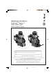
ProMinent ® Operating Instructions ProMinent® Sigma/ 2 S2Ba (Basic Type) S2Ca (Control Type) STOP START S2Ba S2Ca S2Ba ___ ___ ___ ___ ___ ___ ___ ___ ___ ___ ___ ___ S2Ca ___ ___ ___ ___ ___ ___ ___ ___ ___ ___ ___ ___ ___ ___ ___ Please enter the identity code of the device here.
Imprint Imprint Operating Instructions for ProMinent® Sigma/ 2 S2Ba/S2Ca Translation of the original operating manual © ProMinent Dosiertechnik GmbH, 2002 ProMinent Dosiertechnik GmbH Im Schuhmachergewann 5-11 69123 Heidelberg · Germany info@prominent.com www.prominent.com Subject to technical modifications. ® ProMinent Page 2 BA_SI_036_06_10_EN.p65 2 08.06.
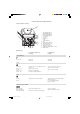
Control elements and key functions Control elements: overview 4 3 2 1 5 16 6 7 8 9 10 15 14 13 12 11 1 2 3 4 5 6 7 8 9 10 11 12 13 14 15 16 Operating light (green) Warning light (yellow) Error warning light (red) Stroke length adjuster LCD display UP key DOWN key P key STOP/START key i key Relay output (optional) Metering monitor socket Float switch socket External control socket Diaphragm rupture indicator socket Mains switch Key functions In continuous display mode (operating) In settings mode (
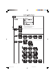
p. 52 Select the operating mode here first, then carry out the settings in the SET menu. Exceptions: Timer and PROFIBUS®. p. 43 p. 51 p. 44 next page BA_SI_036_06_10_EN.p65 4 08.06.
previous page p. 49 p. 48 p. 49 Calib Set Set Set P Set Set p. 34 Calib Set Set p. 50 p. 50 p. 50 BA_SI_036_06_10_EN.p65 5 08.06.
Page 6 BA_SI_036_06_10_EN.p65 ProMinent ® 6 08.06.
Table of contents Page Identcode ordering system 1 9 Notes on safety of ProMinent ® metering pumps 1.1 General notes 12 1.2 Notes on installation, start-up and operation 12 1.3 Notes on maintenance and repair 13 2 14 Product description S2Ba/S2Ca 2.1 Identification of pump type 14 2.2 Design/Functional description 14 3 2.2.1 Functional description, drive 14 2.2.2 Stroke movement 15 2.2.3 Functional description, delivery unit 16 2.2.
Table of contents 6 Control elements 41 7 Settings 42 7.1 Check adjustable values 43 7.2 Change to settings mode 43 7.3 Select operating mode (MODE menu) 43 7.4 Settings for operating mode (SET menu) 44 7.4.1 Settings for “manual” operating mode 44 7.4.2 Settings for “analogue” operating mode (ANALG menu) 44 7.4.3 Settings for “contact” operating mode (CONTCT menu) 46 7.4.4 Settings for “batch” operating mode (BATCH menu) 48 7.5 Settings for programmable functions (SET menu) 7.5.
Identcode ordering system Identcode ordering system Please enter the identcode on the device label into the grey box below. ® ® ProMinent ProMinent BA_SI_036_06_10_EN.p65 Page 9 9 08.06.
Identcode ordering system Identcode ordering system Please enter the identcode on the device label into the grey box below. ® ProMinent Page 10 BA_SI_036_06_10_EN.p65 10 08.06.
Notes on safety of ProMinent ® metering pumps 1 Notes on safety of ProMinent ® metering pumps General user instructions Please read through the following user instructions carefully! They will help you get the best use out of the operating instruction manual. The following are highlighted in the text: • Enumerations 왘 Instructions Operating guidelines: NOTE Notices are intended to make your work easier. and safety guidelines: WARNING Describes a potentially dangerous situation. If not avoided.
Notes on safety of ProMinent ® metering pumps 1.1 General notes WARNING • Only EX pump: Please thoroughly read the chapter “Important Additions for Metering Pumps in the EX Area” of the “General Operating Instructions ProMinent Motor Metering Pumps and Hydraulic Accessories”! • The equipment/devices may only be used for their intended purpose.
Notes on safety of ProMinent ® metering pumps IMPORTANT • Set stroke length only with pump in operation! • Pull the red plug for venting the gear unit during initial operation of the Sigma/ 2 metering pump (refer to Fig.
Product description S2Ba/S2Ca 2 Product description S2Ba/S2Ca Use for intended purpose • The pump is designed as a liquid medium metering pump; it serves the purpose of metering liquid medium within the specified line system! • In potentially explosive atmospheres in zone 1, device category II 2G of explosion group II C, the pump must only be operated according to the relevant type plate (and the respective EC Declaration of Conformity) for pumps for potentially explosive atmospheres complying with Direc
Product description S2Ba/S2Ca Fig. 5 61_01-101_00_25-01 2.2.2 Stroke movement a) Stroke progression at max. stroke rate and stroke length b) At reduced stroke length Stroke speed + Delivery stroke – Intake stroke 0 180 360 Angle reduced stroke length Fig. 6 Set stroke length dependent on the required delivery capacity. 30 % 30% 75 % 75% 0 50 25 75 20 0 0 25 5 0 5 10 Fig.
Product description S2Ba/S2Ca 2.2.3 Functional description, delivery unit The heart of the liquid end is the multi-layer safety diaphragm (2) patented by ProMinent. It hermetically seals the delivery chamber of the liquid end (4) and produces a displacement in the dosing head. The end disc (5) made of chemically-resistant plastic, together with the safety diaphragm (13) separates the drive housing from the delivery unit and protects the drive from dust and corrosion.
Product description S2Ba/S2Ca 2.2.4 Integrated overflow valve with bleeder function Task: The task of the overflow valve is to protect the motor and gear unit against impermissible overpressure caused by the metering pump. This function is produced by a spring-loaded ball. A pressure relief mechanism for the bleeder function is provided. Design and functional description (refer to Fig. No.
Product description S2Ba/S2Ca 102 132 130 139 133 128 Overflow valve Sigma/ 2 liquid end, 16 bar SST Identcode Type: 16050, 16090, 16130 Overflow valve Sigma/ 2 liquid end, 7 bar SST Identcode Type: 07120, 07220 Overflow valve Sigma/ 2 liquid end, 4 bar SST Identcode Type: 04350 Fig.
Product description S2Ba/S2Ca Technical data Corresponding to the type of pump, overflow valves are available for pressure stages pnom 4, 7, 10, 12 and 16 bar with (1.05 ... 1.15) xpnom opening pressure. Material in contact with metered medium Material version Balls Integrated overload valve PVT Ceramic / glass* PDFE/FPM or EPDM SST Stainless steel 1.
Product description S2Ba/S2Ca Design and function description 1 7 6 5 Fig.
Product description S2Ba/S2Ca WARNING • Only EX pump: Please thoroughly read the chapter “Important Additions for Metering Pumps in the EX Area” of the “General Operating Instructions ProMinent Motor Metering Pumps and Hydraulic Accessories”! IMPORTANT • With the S3Ba, the customer should install a diaphragm rupture signal monitor with electrical diaphragm sensors or ensure that the metering pump will stop after a diaphragm rupture signal.
Technical data 3 Technical data WARNING Only with modified version: Observe the “Enhancement with modified version” at the end of the chapter in all cases! It replaces and supplements the technical data! 3.1 Technical data Sigma/ 2 3.1.1 Capacity data Technical data S2Ba at 50 Hz operation Feed rate at maximum back pressure Max.
Technical data Technical data S2Ca Feed rate at maximum back pressure Max. stroke rate Suction lift Admissible priming pressure suction side Connection suction / discharge side Shipping weight Pump type Sigma bar l/h ml/stroke strokes/min.
Technical data 3.1.2 Dimensions Sigma/ 2 S2Ba Tube nozzle sv d16 S with thread DIN ISO 228-G3/4 C Connection variations L Ø 165 B A ØG PVDF Ø16 185 PP/PVC/PTFE max. 40 SS F 6.5 120 44 K 136 27+7 28 D 120 225 E Fig.
Technical data 3.1.3 Dimensions Sigma/ 2 S2Ca Tube nozzle sv d16 S with thread DIN ISO 228-G3/4 A C B ØG 441 Ø 165 185 A Ø16 max. 40 27+7 6.5 120 F 44 28 79.5 120 136 222 D K E Fig.
Technical data 3.1.4 Dimensions Sigma/ 2 S2Ba T ØP ØN 170 217 V E A-A 120 8 225 44 191 ØD ØS ØM 120 A Fig. 14 A 61_01_101_00_27_73 K Dimensions Sigma/ 2 (in mm) Motor flange ØP ØM ØN B 14/105 105 85 70 56 C/138 5.43⬙ 5.88⬙ 4.5⬙ B 14/160 160 130 110 B 14/200 200 165 130 B 5/140* 140 115 95 ØS ØD E T K L V 19 29 3,5 5 16,3 288 0.62⬙ 1.14⬙ 0.16⬙ 0.2⬙ 0.72⬙ 12.
Technical data Fuse data IMPORTANT • The motors are not fuse-protected. Fit a motor circuit breaker! • When connecting the motor, make sure that it rotates in the correct direction (see Fig. 11). direction of rotation Protection against accidental contact and moisture (IP) Motor: IP 55 DIN EN 60034-5 (in accordance with DIN VDE 0470 Part 1, corresponds to EN 60529 and IEC 529). Air humidity Air humidity: maximum 90 % relative humidity, non-condensing.
Technical data 3.1.9 Electrical data, pacing relay “Sigma” (for the basic version) Relay input (power supply for the relay board) Input voltage Mains frequency Power consumption 200/230 V AC (180-254 V) 50/60 Hz 10 mA (230 V/50 Hz) 100/115 V AC (90-134 V) 50/60 Hz 15 mA (115 V/60 Hz) 24 V DC (20-28 V) - 10 mA at 24 V DC Relay output Voltage, max. 24 V DC Current, max. 100 mA Hook up duration Standard 100 ms adjustable The contacts are zero volt. 3.1.
Technical data Supplement for modified version (For Identcode feature “Type“: “M modified“) [Affix label with modified data here!] ® ProMinent BA_SI_036_06_10_EN.p65 Page 29 29 08.06.
Start-up/Maintenance 4 Start-up/Maintenance WARNING • For all metering pumps for metering inflammable media applies: Starting up and emptying only supervised by a competent person. IMPORTANT Observe the safety notes provided in Section 1. 4.1 Start-up All general guidelines in the accompanying ”General operating instructions ProMinent® motordriven metering pumps and hydraulic accessories” apply.
Start-up/Maintenance 4.3 Replacement of wearing parts Replacing diaphragm (see exploded diagrams in appendix!) WARNING • Only EX pump: Please thoroughly read the chapter “Important Additions for Metering Pumps in the EX Area” of the “General Operating Instructions ProMinent Motor Metering Pumps and Hydraulic Accessories”! • Replacement of the diaphragm (see exploded view in the annex). IMPORTANT • Flush liquid end first in the case of hazardous media.
Start-up/Maintenance / Features of the S2Ca metering pumps 5 3 13 4 2 Fig. 17 61_05-103_00_73-03 1 GUIDELINE ON VALVE INSTALLATION In the case of suction problems during installation, place the valves on a firm surface and tap the PTFE ball seat disk lightly with a brass rod and a hammer weighing about 300 g. Let the valves operate in the wet state. approx. 300 g Brass rod 9 mm diam. x approx. 200 mm Fig.
Features of the S2Ca metering pumps NOTE • Sigma control pumps are fitted with a 3-phase WBS motor, but thanks to the internal microprocessor control, are connected directly to a 1-phase line voltage. The connection data of the pump below is therefore different to that of the motor (see chapters “Technical Data” - “Motor Data”, “Identcode Feature” “S”). • The performance data in 3.1.1 are measured with the S2Ba (base model with 3-phase motor).
Features of the S2Ca metering pumps The following functions are available as standard: “Float switch” function: Information on the liquid level in the feed chemical container is transmitted to the S2Ca. This option requires the installation of a 2-stage float switch. This is connected to the “float switch” terminal. “Pause” function: The S2Ca can be stopped by remote control via the “external control” terminal. The “pause” function operates only via the “external control” terminal.
Features of the S2Ca metering pumps 5.3 Sockets, symbols and wiring diagram 4 2 6 7 1 5 Fig.
Features of the S2Ca metering pumps Wiring diagram View of cable connectors from front Universal signal cable (5-core) 5 grey/auxiliary 4 black/ GND 1 brown / pause Blue and black open -> alarm signal Brown and black open -> alarm signal + pump stops 3 blue / analogue for 3 brown pause 2 blue/alarm 1 black GND for 2 white/cod Float switch cable Pause function: brown and black closed -> pump metering Metering monitor cable brown and black open -> alarm + pump stopped for External/contact:
Features of the S2Ca metering pumps Technical data, external contact Semi-conductor switch elements (e.g. transistors in open-collector circuits) or contactors (relays) with a residual voltage of -0.7 V can be used as input switch elements. Controller type 0 (see identity code) Pin 1 = Pause input (activating function) Voltage at open contacts: approx. 5 V Input resistance: 10 kΩ Controller: – zero volts contact (approx. 0.5 mA) – semi-conductor (residual voltage: < 0.
Features of the S2Ca metering pumps Block circuit diagram S2Ca Inputs Empty signal, Outputs Pump, Inside 3 brown/pause warning 2 blue/alarm Level monitor 1 black/GND Fault indicating relay 1 brown/5 V 2 white/cod Metering monitor Flow control 3 blue Metering monitor 4 black/GND Diaphragm rupture sensor 2 blue/alarm 1 black/GND VDE cable: 2 green/NC 1 white /NO 4 brown/C VDE cable: 1 yellow/NO (fault) Fault indicating and pacing relay Diaphragm rupture sensor 4 green/C (fault) 3 white/NO
Features of the S2Ca metering pumps Circuit examples: universal signal cable by customer “External contact“ function (ProMinent® external/contact cable) two-core Cable Pump, inside 2 white/contact 4 brown/GND External activation Pulse rate, e.g. contact water meter “External contact“ function (ProMinent® universal signal cable) five-core 3 blue/analogue 2 white/contact 1 brown/pause 4 black/GND External activation 5 grey/auxiliary Pulse rate, e.g.
Features of the S2Ca metering pumps IMPORTANT • The universal signal cable, the external/contact cable and the level monitor cable should not be less than 1.20 m long, otherwise cable recognition will fail. 5.
Features of the S2Ca metering pumps / Control elements Fig. 21 6 Fig. 24 Control elements Please acquaint yourself with the S2Ca control elements with the help of the “control elements and key functions” overview! Indicators The LCD display supports the operation and setting of the S2Ca with a range of indicators: Stop Aux Pause Error Mem Calib Flow Set The indicators are interpreted as follows: Symbol for P key: The S2Ca is in settings mode.
Settings 7 Settings NOTE • Open out the fold-out page following the title page fully! There you will find the overviews “control elements and key functions” and “operating settings diagram”. • If no keys are pressed within a period of 1 minute, the S2Ca will return to a continuous display.
Settings 7.1 Check adjustable values Before setting up the S2Ca you can check the current settings of adjustable values: Press the i key (“i” as in “info”) when the S2Ca is in continuous display mode (There is no P key symbol in the LCD display). Each time you press the i key you will see a different continuous display. The number of continuous displays depends upon the identity code, the selected operating mode and the connected accessories (see overview “continuous displays”). 7.
Settings • Contact: for contact operation (Identity code, control variant: external 1:1 / external with pulse control) • Batch: for batch operation (Identity code, control variant: external with pulse control) Analog - ANALOG Manual Analog Manual Contact Batch - MANUAL P P Contact - CONTACT Batch 7.4 - BATCH Settings for operating mode (SET menu) NOTE First select the operating mode in the MODE menu! Exceptions: Timer and PROFIBUS®.
Settings • 4 - 20 mA: at 4 mA the S2Ca does not operate at 20 mA the S2Ca operates at 180 max. strokelength Between these two extremes the stroke rate is proportional to the electrical signal. For signals of below 3.8 mA a fault will be detected and the S2Ca will stop (e.g. cable break). • Curve: In the “curve” processing mode you can programme the S2Ca ratios. There are 3 options available: • = straight line • = lower band • = upper band Straight line: .
Settings Lower/upper band: This processing mode allows you to control a pump via an electrical signal as shown in the diagrams below. Lower band Upper band e.g. Alkali pump e.g. acid pump Fmax Fmax P1 F1 P2 F2 P2 F2 P1 F1 0 I1 Fig. 26 I2 20 I [mA] 0 I1 I2 20 I [mA] Fig. 27 Lower band: appears in the LCD display. The S2Ca will operate below I1 at F1. The symbol Above I2, the S2Ca ceases to operate.
Settings In the “contact - identity code: external with external pulse control” you can enter the number of pulses after which a stroke should be carried out. “Contact - identity code: external with external pulse control” is intended for small dosing quantities. The number of strokes per pulse depends upon the factor, which you can enter. This allows you to vary to a certain extent the input pulses by a factor of 1.01 to 99.99 and/or reduce by a factor of 0.01 to 0.
Settings NOTE If a remainder occurs when the factor is processed, the S2Ca counts up the remainder values. When the sum reaches or exceeds “1” the S2Ca will activate a stroke. This ensures that the stroke number corresponds exactly to the factor throughout the dosing operation. The number of input pulses which have not been processed are stored by the S2Ca in the stroke memory. The stroke buffer is limited to the batch size when memory is not activated (- with “Memory” at 65535 stokes).
Settings 7.5 Settings for programmable functions (SET menu) The following programmable function settings menus appear in all operating modes: • Calibrate (CALIB menu) • Auxiliary frequency (AUX menu) • Flow (FLOW menu, available only if flow monitor is connected) 7.5.1 Settings for “calibration” function (CALIB menu) P The S2Ca can also run in calibration mode. The corresponding continuous displays show the current dosing quantities or the feed rate.
Settings 7.5.2 Settings for “auxiliary frequency” function (AUX menu) The programmable function “auxiliary frequency” allows switching to a different stroke frequency, which can be set in the AUX menu. It can be activated via the “external control” terminal. When the auxiliary frequency is activated, “aux” appears in the LCD display. This auxiliary frequency overrides the current stroke frequency set for the selected operating mode. 7.5.
Operating 8 Operating WARNING • Only EX pump: Please thoroughly read the chapter “Important Additions for Metering Pumps in the EX Area” of the “General Operating Instructions ProMinent Motor Metering Pumps and Hydraulic Accessories”! This section describes all operating options available to you when the S2Ca is in continuous display mode (no P key symbol in the LCD display).
Operating / Troubleshooting Batch size Priming Cancel error In “batch” operating mode: The batch size can by changed from the “batch size/remaining litres” display. The S3Ca returns to the original continuous display a few seconds after the batch size has been reset. The “priming” function is activated by pressing both arrow keys at the same time (in “Stroke rate” permanent display). Error messages are cancelled by pressing the P key briefly.
Troubleshooting Green LED indicator (operating display) is not lit Cause Remedy Incorrect or no mains voltage. 왘 Use the recommended mains voltage as given in the voltage specification on the nameplate. Error Messages Red LED display is lit, “Error” and “MINIM” flash in the display Cause Remedy Fluid level in the chemical storage tank has reached “liquid level low, stage 2”. 왘 Fill the chemical supply container.
Troubleshooting / Decommissioning and disposal Red LED display is lit, “Error” appears in the display and “FAN” is flashing Cause Remedy Fault related to fan in pump housing. 왘 Check fan and replace if necessary. 왘 Press the P key (reset function). Red LED display is lit, “Error” appears in the display and “SYSTEM” is flashing Cause Remedy Controller fault. 왘 Disconnect the pump from the mains and reconnect. If the error message continues, send the pump back to ProMinent.
Spare parts and accessories 11 Spare parts and accessories CAUTION The assembly and installation of ProMinent® metering pumps with other-make parts that are not tested and recommended by ProMinent are not permitted and can lead to personal injury and damage to property for which no liability shall be accepted! Spare parts You will find the order numbers for the wearing parts in the exploded view drawings in the annex. If you require further parts, please order the “Spare parts list ProMinent® Sigma/ 2”.
Q (I/h Q (I/h BA_SI_036_06_10_EN.p65 Page 56 08.06.
BA_SI_036_06_10_EN.p65 57 Q (I/h Q (I/h ProMinent ® 08.06.
Annex Motor data sheet ® ProMinent Page 58 BA_SI_036_06_10_EN.p65 58 08.06.
EC Declaration of Conformity For pumps without Ex protection: ® ProMinent BA_SI_036_06_10_EN.p65 Page 59 59 08.06.
EC Declaration of Conformity For pumps with Ex protection: The EC conformity declarations, the EC series prototype test reports and the operating manuals for the individual components are also supplied with the pump. ® ProMinent Page 60 BA_SI_036_06_10_EN.p65 60 08.06.
Exploded diagrams of liquid ends Delivery unit Sigma/ 2 350-DN 25 PVT for identity code types: S2Ba/S2Ca 04350, 07120, 07220 Delivery unit Sigma/ 2 130-DN 15 PVT for identity code types: S2Ba/S2Ca 16050, 16090, 16130 Valve spring ** Valve ball Ball seat Valve complete DN 25/PVT* Part no. 740615 Valve complete DN 15/PVT* Part no. 792517 Multi-layer diaphragm FM 350* Part no. 1033422 Multi-layer diaphragm FM 130* Part no. 1029771 Valve complete DN 25/PVT* Part no. 740615 Valve complete DN 15/PVT* Part no.
Exploded diagrams of liquid ends Delivery unit Sigma/ 2 350-DN 25 SST for identity code types: S2Ba/S2Ca 04350, 07120, 07220 Delivery unit Sigma/ 2 130-DN 15 SST for identity code types: S2Ba/S2Ca 16050, 16090, 16130 Valve complete FM 350 SST * Part no. 803708 Valve complete FM 130 SST * Part no. 809404 Valve spring ** Valve ball Multi-layer diaphragm FM 350 * Part no. 1033422 Multi-layer diaphragm FM 130 * Part no. 1029771 Ball seat Valve complete FM 350 SST * Part no.
Exploded diagrams of liquid ends Delivery unit Sigma/ 2 350-DN 25 PVT for identity code types: S2Ba/S2Ca 04350, 07120, 07220 Delivery unit Sigma/ 2 130-DN 15 PVT for identity code types: S2Ba/S2Ca 16050, 16090, 16130 * * * * * * Overflow valve assy 10 bar PVA Part no. 1018947 Overflow valve assy 7 bar PVA Part no. 740811 Overflow valve assy 4 bar PVA Part no. 740812 Spare parts kit ÜV 10 bar PVA Part no. 1031201 Spare parts kit ÜV 7 bar PVA/SSA Part no.
Anschriften- und Liefernachweis durch den Hersteller / Addresses and delivery through manufacturer / Adresses et liste des fournisseurs fournies par le constructeur / Para informarse de las direcciones de los distribuidores, dirigirse al fabricante: ProMinent Dosiertechnik GmbH Im Schuhmachergewann 5-11 69123 Heidelberg Germany Tel.: +49 6221 842-0 Fax: +49 6221 842-419 info@prominent.com www.prominent.com ProMinent ® Anschr_Lief_Herst_A4_4spr.p65 2 29.07.