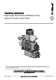
Operating instructions Diaphragm Motor-Driven Metering Pump Sigma/ 2 Control Type S2Ca PK_2_115 Two sets of operating instructions are required for the safe, correct and proper operation of the metering pumps: The product-specific operating instructions and the "General Operating Instructions for ProMinent® motor-driven metering pumps and hydraulic accessories". Both sets of operating instructions are only valid when read together.
ProMinent Dosiertechnik GmbH Im Schuhmachergewann 5-11 69123 Heidelberg Germany Telephone: +49 6221 842-0 Fax: +49 6221 842-617 email: info@prominent.com Internet: www.prominent.
Table of contents Table of contents 1 Identity code S2Ca.......................................................................... 5 2 Safety chapter................................................................................. 8 3 Storage, transport and unpacking................................................. 11 4 Overview of equipment and control elements............................... 13 5 Functional description.................................................................... 15 5.1 5.
Table of contents 12.2.2 Warning Alerts.................................................................. 63 12.3 All Other Faults................................................................... 63 13 Decommissioning.......................................................................... 64 14 Technical data............................................................................... 66 14.1 Performance data................................................................ 14.2 Shipping weight......
Identity code S2Ca 1 Identity code S2Ca S2Ca Sigma 2, Control Type, Version a Product range S2C a Drive type H Main power end, diaphragm Type Performance bar l/h**** 16050 10* 60 16090 10* 95 16130 10* 136 07120 7 148 07220 7 232 04350 4 350 Dosing head material PV PVDF SS Stainless steel Seal material T PTFE Displacement S Multi-layer safety diaphragm with optical break indicator A Multi-layer safety diaphragm with rupture signalling with “pump stops” func‐ tion B Multi-la
Identity code S2Ca S2Ca Sigma 2, Control Type, Version a 7 Union nut and PVDF hose nozzle 8 Union nut and SS hose nozzle Version 0 With ProMinent® Logo 1 Without ProMinent® Logo Electric power supply U 1 ph, 100-230 V, ±10 %, 50/60 Hz Cable and plug A 2 m European B 2 m Swiss C 2 m Australian D 2 m USA Relay 0 No relay 1 Fault indicating relay N/C 1x changeover contact 230 V- 2 A 3 Fault indicating relay magnetic 1x changeover contact 230 V- 2 A 4 as 1 + pacing relay 2x N/O 24 V 100 mA
Identity code S2Ca S2Ca Sigma 2, Control Type, Version a 3 As 1 + message in the event of a manual stop Dosing monitor 0 Input with pulse evaluation Stroke length adjustment 0 Manual C Manual + calibration FPM = fluorine rubber * for SST = 16 bar ** Standard with tube nozzle in the bypass Threaded connection on request.
Safety chapter 2 Safety chapter Explanation of the safety information Warning signs denoting different types of danger The following signal words are used in these operating instructions to identify different severities of a hazard: Signal word Meaning WARNING Denotes a possibly hazardous sit‐ uation. If this is disregarded, you are in a life-threatening situation and this can result in serious inju‐ ries. CAUTION Denotes a possibly hazardous sit‐ uation.
Safety chapter Safety information WARNING! Warning of hazardous or unknown feed chemical Should a hazardous or unknown feed chemical be used, it may escape from the hydraulic components when working on the pump. – – Take appropriate protective measures before working on the pump (protective eyewear, protective gloves, ...). Read the safety data sheet on the feed chemical. Drain and flush the liquid end before working on the pump.
Safety chapter Information in the event of an emergency In the event of an electrical accident, disconnect the mains cable from the mains or press the emergency cut-off switch fitted on the side of the system! If feed chemical escapes, also depressurise the hydraulic system around the pump as necessary. Adhere to the safety data sheet for the feed chemical.
Storage, transport and unpacking 3 Storage, transport and unpacking Safety information WARNING! Only return metering pumps for repair in a cleaned state and with a flushed liquid end - refer to the section on decommis‐ sioning! Only send metering pumps with a filled in Decontamination Declaration form. The Decontamination Declaration consti‐ tutes an integral part of an inspection / repair order.
Storage, transport and unpacking Ambient conditions Data Minimum storage and transport tempera‐ ture -10 °C Maximum storage and transport tempera‐ ture +50 °C Maximum air humidity * * non-condensing 12 Value Unit 95 % rel.
Overview of equipment and control elements 4 Overview of equipment and control elements Overview of equipment 1 5 2 3 4 6 P_SI_0068_SW Fig. 1: Overview of equipment S2Ca 1 2 3 4 Drive motor Drive unit Control unit Liquid end Control elements 1 2 P_SI_0088_SW Fig.
Overview of equipment and control elements 1 2 43 5 10 9 8 7 6 P_SI_0079_SW Fig. 3: Block diagram Sigma Control 1 1 2 3 4 5 6 7 8 9 10 Stroke adjustment dial LCD screen Operating indicator (green) Warning indicator (yellow) Fault indicator (red) i [key ] [START/STOP] key [P] key [DOWN] key [UP] key 1 2 3 4 5 6 7 P_SI_0078_SW Fig.
Functional description 5 Functional description 5.1 Drive unit The metering pump is an diaphragm pump, the stroke length of which can be adjusted. An electric motor (1) drives the pump. A worm gear (2) steps down its drive rotation A cam (3), in conjunction with the uptake fork (8) converts this into an oscillation movement of the slide rod (4). A return spring (5) presses the uptake fork together with the slide rod positively against the cam thus producing the reciprocal stroke.
Functional description 5.2 Liquid end The diaphragm (2) hermetically shuts off the pump volume of the dosing head (4) towards the outside. The suction valve (1) closes as soon as the diaphragm (2) is moved in to the dosing head (4) and the feed chemical flows through the discharge valve (3) out of the dosing head.
Functional description 1 2 3 4 5 P_SI_0019 Fig. 8: Integral relief valve 1 2 3 4 5 Spring, large Ball Rotary dial Spring, small Hose connection 5.4 Multi-layer safety diaphragm The multi-layer safety diaphragm has the same function as the conven‐ tional double diaphragm system with working and safety diaphragms; how‐ ever it also has the advantage that both diaphragms are joined together in a single unit.
Functional description 1 7 6 5 4 2 3 P_SI_0020_SW Fig. 10: Section through the Sigma diaphragm rupture warning system ("Visual break indicator" version) 1 2 3 4 5 6 7 Working layer (≙ operating diaphragm) Safety layer (≙ safety diaphragm) Flap Piston Diaphragm rupture sensor Cylinder, red Cover, transparent 5.
Functional description 5.6 Functions The following functions can be selected using the SET menu: "Calibrate" function: (Identity code, stroke length adjustment: manual + calibration) The pump can also be operated in the calibrated state in all operating modes. In this case, the corresponding continuous displays can then indicate the metering volume or the capacity directly. Calibration is maintained within a stroke rate range of 0 - 180 strokes/min.
Functional description 5.8 Function and fault Indicator The operating and fault statuses are indicated by the three LED indicators and the “Error” identifier on the LCD screen, see also the "Trouble‐ shooting" chapter. 5.9 LCD screen If a fault occurs, the identifier “Error” appears and an additional error mes‐ sage. 5.10 LED indicators Operating indicator (green): The operating indicator illuminates if during pump operation there are no incoming fault or warning messages.
Assembly 6 Assembly CAUTION! Danger of material damage The device can be damaged by incorrect or improper storage or transportation! – – – – The unit should only be stored or transported in a well packaged state - preferably in its original packaging. Only transport the unit when the red gear bleeding plug is pushed in. The packaged unit should also only be stored or trans‐ ported in accordance with the stipulated storage condi‐ tions.
Assembly Space requirement CAUTION! Danger from incorrectly operated or inadequately maintained pumps Danger can arise from a poorly accessible pump due to incorrect operation and poor maintenance. A – – A Ensure that the pump is accessible at all times. Adhere to the maintenance intervals. Position the pump so that control elements such as the stroke length adjustment knob, the indicating dial A or the oil inspection window are accessible. P_MOZ_0018_SW Fig.
Installation 7 Installation CAUTION! Danger of personnel injury and material damage The disregard of technical data during installation may lead to personal injuries or damage to property. – Observe the technical data- refer to chapter "Technical Data" and, where applicable, the operating instructions of the accessories. 7.
Installation CAUTION! Warning against the discharge line bursting With a closed discharge line (e.g. due to a clogged discharge line or by closing a valve), the pressure that the metering pump generates can reach several times the permissible pressure of the system or the metering pump. This could lead to lines bursting resulting in dangerous consequences with aggressive or toxic feed chemicals.
Installation CAUTION! Warning of backflow A back pressure valve, spring-loaded injection valve, relief valve, foot valve or a liquid end do not represent absolutely leak-tight closing elements. – For this purpose use a shut-off valve, a solenoid valve or a vacuum breaker. CAUTION! Warning of illegal operation Observe the regulations that apply where the unit is to be installed.
Installation CAUTION! Warning of feed chemical spraying around If no relief valve was connected to the overflow line, the feed chemical sprays out of the hose connection as soon as the relief valve opens. – An overflow line must always be connected to the inte‐ gral relief valve and be fed back to the storage tank or if required by the regulations - into a special storage tank. CAUTION! Danger of cracking Cracking of the PVT liquid end can occur if a metal overflow line is connected to the relief valve.
Installation CAUTION! Warning of unnoticed diaphragm rupture Only above approximately 2 bar system back pressure is a signal generated upon a diaphragm rupture. – Only rely on the diaphragm rupture sensor at back pres‐ sures greater than 2 bar. 7.2 Installation, electrical General safety notes WARNING! Danger of electric shock Unprofessional installation may lead to electric shocks. – – All cable cores cut to length must be provided with cable end sleeves.
Installation For technical data see "Technical Data" chapter. Pacing relay (option) 1. Install the cable which originates from the pacing relay - see the figure in the chapter entitled "Overview of equipment and control elements": Cable A, left. The cable polarity is unimportant. 2. Install the power supply cable to the pacing relay PCB - see the figure in the chapter entitled "Overview of equipment and control elements": Cable B, right.
Installation Fig. 21: Cable conductor assignments To pin VDE cable Contact CSA cable 1 white NO (normally open) white 2 green NC (normally closed) red 4 brown C (common) black As a NC fault indicating relay - the relay closes immedi‐ ately after the power is switched on and opens in the event of a fault. As a N/O fault indicating relay, the relay closes in the event of a fault.
Installation As a NC fault indicating relay - the relay closes immedi‐ ately after the power is switched on and opens in the event of a fault. As a N/O fault indicating relay, the relay closes in the event of a fault. – – Output relay Data Value Unit Maximum voltage 250 VDC (50/60 Hz) Maximum current 16 A (resis‐ tive) Closing duration - Service life * > 30 000 Play * at rated load Behaviour: - see identity code The contacts are potential-free. Output relay Pin assignment P_SI_0043 Fig.
Installation External control Wiring diagram View of the cable plug from the front Level switch cable 3 2 Universal control wire (5-core) for 2 1 for 3 5 1 blue + black: open -> Alarm message brown + black: open -> Alarm message + Pump stopped 2 4 for External/Contact: white + black: close -> Start contact for pump (Pause function inactive?: brown + black: closed) 3 4 black / GND 3 blue 2 white / Cod.
Installation Technical data "external control" 2 1 Semi-conductor switch elements with a residual voltage of -0.7 V (e.g. transistors in open-collector circuits) or contacts (relays) can be used as input switch elements. 3 4 5 P_BE_0014_SW Control type 0 (see identity code) Pin Pin 1 = Pause input (activating func‐ tion) Voltage with open contacts: approx. 5 V Input resistance: 10 kΩ Control: n n 2 = contact input Potential-free contact (approx. 0.
Installation Control type 1 (see identity code) Pin Pin 1 = Pause input (activating func‐ tion) Voltage with open contacts: approx. 5 V Input resistance: 10 kΩ Control: n n 2 = contact input Voltage with open contacts: approx. 5 V Input resistance: 10 kΩ Control: n n 3 =Analog input* Potential-free contact (approx. 0.5 mA) Semiconductor switch (residual voltage < 0.7 V) Potential-free contact (approx. 0.5 mA) Semiconductor switch (residual voltage < 0.7 V) min.
Installation Block diagram Sigma Control Inputs Outputs Pump, inside Empty signal 3 brown / Pause Warning 2 blue / Alarm 1 black / GND Level sensor VDE cable: 2 green / NC (fault alert) 1 brown / 5 V Stroke sensor Flow Control 2 white / Cod.
Installation Universal control wire connection diagram Site end Function "External Contact" (ProMinent external/contact cable) 2-core Cable 2 white / Contact 4 brown / GND Pump, inside External activation GND Pulse frequency, e.g. contact water meter, PLC etc. Function "External Contact" (ProMinent universal control wire) 5-core 3 blue / Analog 2 white / Contact 1 brown / Pause 4 black / GND 5 grey /Auxiliary External activation GND Pulse frequency, e.g. contact water meter, PLC etc.
Installation 7.2.2 Pump, power supply 1. Install an emergency cut-off switch or include the pump in the emer‐ gency cut-off management of the system. 2. Install the pump cable. – Key electrical data can be found on the pump name‐ plate. 7.2.3 Other units Other units Install the other units according to their supplied documentation.
Adjustment 8 Adjustment For supplementary information see "Control elements and key functions" in the chapter "Overview of equipment and control elements" and "Operating/setting overview" in the appendix. The pump control returns to the continuous display, as soon as no key has been pressed for one minute. 8.1 Basic principles of pump adjustment Installation option flashes Continuous display B0082 Fig.
Adjustment Changing adjustable values Press the arrow keys [UP] or [DOWN]. ð The flashing digit or number counts up or down. Confirming adjustable values Under "change individual digits": confirm each digit by pressing the [P] key. ð Upon confirming the last individual digit, the display simultane‐ ously changes to the next menu option or into a continuous dis‐ play. Under "change a number": Press the [P] key 1x. ð The display simultaneously changes to the next menu option or into a continuous display.
Adjustment To match the pump to your process requirements, you must observe the following procedure: 1. In the “MODE” menu select the operating mode. 2. If necessary make the settings for this operating mode in the “SET” menu. 1. MODE menu CODE menu Continuous display 2s P 2. SET menu CLEAR window B0084 Fig. 28 Exceptions: Timer and PROFIBUS®. Note the diagram. 8.
Adjustment Analog - ANALOG Manual Analog Manual CONTACTBatch - MANUAL P P CONTACT - CONTACT Batch Continuous display - BATCH B0085 Fig. 29 8.5 Operating mode settings (SET menu) First in the “MODE” menu select the operating mode! Exceptions: Timer and PROFIBUS®. In the “SET” menu, you can make various settings dependent on the selected operating mode.
Adjustment Continuous display B0086 Fig. 30 You can select three types of current signal processing: n “0 - 20 mA” : At 0 mA the pump is stationary. At 20 mA the pump works at the maximum stroke rate. Between these values, the stroke rate is proportional to the cur‐ rent signal. “4 - 20 mA” : – At 4 mA the pump is stationary. – At 20 mA the pump works at the maximum stroke rate. – Between these values, the stroke rate is proportional to the cur‐ rent signal. – For current signals less than 3.
Adjustment Fmax P2 F2 P1 F1 0 I2 I1 20 I [mA] B0088 Fig. 32 F1 Stroke rate at which the pump should operate with current I1 F2 Stroke rate at which the pump should operate with current I2 Plot a diagram similar to the one above - with values for (I1, F1) and (I2, F2) – so that you can set the pump control as required. Upper/lower sideband Using these processing types, you can control a metering pump using the current signal as shown in the diagrams below.
Adjustment Fault processing Under menu option “ER” (Error) you can activate error processing for the “Curve” processing type. For current signals below 3.8 mA, a fault mes‐ sage appears and the pump stops. 8.5.3 "Contact" operating mode settings (CNTCT menu) Alongside those described in more detail in the chapter "Programmable function settings (SET menu)" the “CNTCT” menu is also available in “Contact” operating mode via the “SET” menu.
Adjustment Example Example table Step-up Reduction Factor Pulse (sequence) Number of strokes (sequence) 1 1 1 2 1 2 25 1 25 99.99 1 99.99 1.50 1 1.50 (1 / 2) 1.25 1 1.25 (1 / 1 / 1 / 2) 1 1 1 0.50 2 1 0.50 10 1 0.50 100 1 0.50 4 1 0.50 2.5 (3 / 2) (1 / 1) 0.50 1.33 (2 / 1 / 1) (1 / 1 / 1) Explanation of step-up Factor Pulse and strokes with a factor 1 ... 1 stroke is executed per pulse with a factor 2 ... 2 strokes are executed per pulse with a factor 25 .
Adjustment "Memory" function extension You can also activate the "Memory" function extension (identifier “Mem” appears on the LCD screen; “Mem” = memory). When "Memory" is acti‐ vated, the pump software adds up the remaining strokes , which could not be processed, up to the maximum capacity of the stroke memory of 65,535 strokes. If this maximum capacity is exceeded, the pump goes into fault mode.
Adjustment 8.6.1 “Calibrate” function settings (CALIB menu) Continuous display B0093 Fig. 37 The pump can also be operated in the calibrated state. In this case, the corresponding continuous displays then indicate the metering volume or the capacity directly. The calibration is maintained when the stroke length is altered by up to ±10 scale divisions (for a set stroke length of 40 % this corresponds to a range from 30 % ... 50 %).
Adjustment Consequence: n n n The corresponding continuous displays indicate the calibrated values. Total number of strokes and total litres are set to "0" by calibrate. The pump is in the STOP state. 8.6.2 “Auxiliary frequency” function settings (AUX menu) Continuous display B0094 Fig. 38 The programmable function "Auxiliary frequency" facilitates the activating of an auxiliary stroke rate, which can be set in the “AUX” menu. It can be activated via the "External control" terminal.
Adjustment In the first menu option, you can set either CODE 1 or CODE 2 (both use the same number). n n n Select “CODE 1” , to block adjustment mode (① in "Operating / adjustment overview" in the appendix). In the next menu option, enter the number you want to use as the code. Select “CODE 2” , to block the option to adjust the directly changeable values in the continuous displays (① in "Operating / adjustment over‐ view" in the appendix).
Operation 9 Operation This chapter describes all the operating options available to you if the pump control is showing a continuous display - then the display does not contain the symbol for the [P] key. – – For supplementary information, please read the over‐ views "Control elements and key functions" and see the "Operating/setting diagram" at the end of the operating instructions. Also take note of the overview "Continuous displays".
Operation Changing directly changeable variables To change a value, see below, directly in the corresponding continuous display, press one of the [arrow keys] until the [Set] identifier appears. (The delay period has been programmed in to prevent unintentional changing of values.) If “CODE 2” was set, then after pressing an [arrow key], the code must first be entered.
Operation Continuous display STOP Stop/start pump START 2 Change directly changeable variables Prime P P i P Start batch (only in "Batch" operating mode) Acknowledge errors Check adjustable values 2s 1 1 = Lock (CODE 1) 2 = Lock (CODE 2) Adjustment Mode B0098 9.
Maintenance 10 Maintenance Safety information WARNING! It is mandatory that you read the safety information and specifications in the "Storage, Transport and Unpacking" chapter prior to shipping the pump. CAUTION! Warning of feed chemical spraying around Feed chemical can spray out of the hydraulic components if they are manipulated or opened due to pressure in the liquid end and adjacent parts of the system.
Maintenance Standard liquid ends: Interval Maintenance work Personnel After approx. 5,000 oper‐ ating hours Change gear oil - refer to "Changing gear oil" in this chapter. Instructed personnel Quarterly Check the oil level. Quarterly* n n n n n n Technical personnel Check that the metering lines are fixed firmly to the liquid end. Check that the suction valve and discharge valve are correctly seated.
Maintenance Prerequisites: Gear oil according to the "Ordering information" chapter is available. 54 1. Start up the pump. 2. Slowly pour gear oil through the vent screw (1) opening until the oil inspection window (3) is half covered. 3. Allow the pump to run for a further 1... 2 minutes 4. Replace the vent screw (1).
Repairs 11 Repairs Safety information WARNING! It is mandatory that you read the safety information and specifications in the "Storage, Transport and Unpacking" chapter prior to shipping the pump. CAUTION! Warning of feed chemical spraying around Feed chemical can spray out of the hydraulic components if they are manipulated or opened due to pressure in the liquid end and adjacent parts of the system.
Repairs 1. Unscrew the valve from the liquid end. 2. Screw the valve cap (5) on its suction side - see diagram. 3. Carefully remove the parts from the valve body (2). 4. Replace the worn parts. 5. Clean the remaining parts. 6. Check all parts. 7. Insert the valve ball (3 and the valve seat (4). 8. Screw on the valve cap (5). 1 2 3 4 5 P_SI_0013_SW Fig.
Repairs 11.2 Replacing the metering diaphragm Third party spare parts for the pumps may lead to problems when pumping. – – Use only original spare parts. Use the correct spare part kits. In case of doubt, refer to the exploded views and ordering information contained in the "Supplementary information CD for ProMinent® pump operating instructions". Personnel: n Technical personnel Requirements: n n n If necessary take protective measures. Observe the safety data sheet for the feed chemical.
Repairs 3 A 12. Flap Tolerance range Should this not work, remove dirt or swarf out of the thread and screw the diaphragm correctly onto the drive axle this time. ð If this is still unsuccessful, contact ProMinent-ProMaqua cus‐ tomer service. 13. Place the dosing head with the screws onto the diaphragm - the suction connector must be pointing downwards in the pump's fitting position. 14. Tighten the screws gently to start with. 15. Screw the diaphragm rupture sensor into the dosing head. 16.
Repairs Checking the condition of the diaphragm rupture sensor 1. If the inside of the diaphragm rupture sensor has become damp or dirt has penetrated it: replace. 1 7 6 5 4 2 3 P_SI_0020_SW Fig. 44: Section through the Sigma diaphragm rupture warning system ("Visual break indicator" version) 1 2 3 4 5 6 7 Working layer (≙ operating diaphragm) Safety layer (≙ safety diaphragm) Flap Piston Diaphragm rupture sensor Cylinder, red Cover, transparent 2.
Repairs 6. After a successful test, screw the transparent cover onto the dia‐ phragm rupture sensor and then continue at the top by fitting the diaphragm. Electrical diaphragm rupture sensor 1. Press the piston of the diaphragm rupture sensor with a blunt, smooth object into the dosing head (approximately 4 mm) until the monitor triggers alarm. CAUTION! Feed chemical may escape If the expandable flap of the diaphragm is damaged, then feed chemical can escape when there is a dia‐ phragm rupture.
Troubleshooting 12 Troubleshooting Safety information WARNING! Warning of hazardous or unknown feed chemical Should a hazardous or unknown feed chemical be used, it may escape from the hydraulic components when working on the pump. – – Take appropriate protective measures before working on the pump (protective eyewear, protective gloves, ...). Read the safety data sheet on the feed chemical. Drain and flush the liquid end before working on the pump.
Troubleshooting 12.2 12.2.1 Faults with error message Fault alerts Fault description Cause Remedy The red LED indicator illuminates, on the dis‐ play, the identifiers “Error” and “MINIM” flash. The liquid level in the storage tank has reached "liquid level low 2nd stage". Fill storage tank. The red LED indicator illuminates, on the dis‐ play, the identifiers “Error” and “ANALG” flash.
Troubleshooting Fault description Cause Remedy The red LED indicator illuminates, on the dis‐ play, the identifiers “Error” and “MEM” flash. Stroke memory overflow has occurred. Eliminate cause. 12.2.2 Press [P] key - bear in mind the consequences for your process. Warning Alerts Fault description Cause Remedy Green LED indicator illuminates. The liquid level in the storage tank has reached "liquid level low 1st stage". Fill storage tank.
Decommissioning 13 Decommissioning Decommissioning WARNING! Danger of an electric shock When working on the motor or electrical auxiliary equipment, there is a danger of an electric shock. – – Before working on the motor, take note of the safety instructions in its operating instructions! Should external fans, servomotors or other auxiliary equipment be installed, these should also be discon‐ nected and checked that they are voltage free.
Decommissioning CAUTION! Danger of damage to the device The device can be damaged by incorrect and improper storage or transportation. – (Temporary) decommissioning Personnel: Take into account the information in the "Storage, Trans‐ port and Unpacking" chapter if the system is decommis‐ sioned for a temporary period. n Technical personnel 1. Disconnect the pump from the mains power supply. 2. Depressurise and bleed the hydraulic system around the pump. 3.
Technical data 14 14.1 Technical data Performance data S2Ca Type Minimum pump capacity at maximum back pressure Max‐ imum stroke rate Suction lift Permis‐ sible pri‐ ming pres‐ sure, suction side Connector size bar psi l/h gph Strokes/ min ml/stroke m WS bar R"-DN 16050 PVT 10 145 61 16 90 11.4 7 2 1" - 15 16050 SST 16 232 56 15 90 11.4 7 2 1" - 15 16090 PVT 10 145 109 29 160 11.4 7 2 1" - 15 16090 SST 16 232 99 26 160 11.
Technical data Types Material version Shipping weight kg 07120 ... 04350 14.3 PVT 16 SST 24 Wetted materials Material ver‐ sion Liquid end Suction/dis‐ charge con‐ nector Seals* / ball seat Balls Springs Integral relief valve PVT PVDF PVDF PTFE/PTFE Ceramic / glass ** Hastelloy C PVDF / FPM or EPDM SST Stainless steel 1.4404 Stainless steel 1.4581 PTFE/PTFE Stainless steel 1.
Technical data 14.4.3 Air humidity Air humidity Data Value Unit Maximum air humidity *: 95 % rel. humidity * non-condensing 14.4.4 Degree of Protection and Safety Requirements Degree of protection Protection against contact and humidity: IP 55 in accordance with IEC 529, EN 60529, DIN VDE 0470 Part 1 Safety requirements Degree of protection: 1 - Mains power connection with protective earth conductor 14.
Technical data Only use the original fuses from ProMinent! It is not sufficient to use a fuse with the above fuse rating. 14.6 Diaphragm rupture sensor b) Reed switch (identity code specification "Stroke sensor": 2) Pin Allocation 1 (white 4.5 V ... 24 V, max. 10 mA 2 (brown) OUT, open collector, 24 V, 20 mA 3 (green) GND Data Value Unit Pulse width (low)* ≥4 ms * depending on the gear and mains frequency The polarity is unimportant.
Technical data 14.8 Gear oil Manufac‐ Name turer Mobil Viscosity class (ISO 3442) Mobil VG 460 Gear 634 * Part no. Volume Quantity, required 1004542 1.0 l 0.5 l * or comparative gear oil 14.
EC Declaration of Conformity 15 EC Declaration of Conformity For pumps without explosion protection: EC Declaration of Conformity We hereby declare, ProMinent Dosiertechnik GmbH Im Schuhmachergewann 5 - 11 D - 69123 Heidelberg that the following designated product complies with the pertinent fundamental safety and health requirements of the EC Directive in terms of its design and construction and in terms of the version marketed by us.
Decontamination declaration 16 72 Decontamination declaration
Operating / adjustment overview 17 Operating / adjustment overview Continuous display Stop/start pump = Lock (CODE 1) = Lock (CODE 2) Change directly changeable variables Prime Start batch (only in "Batch" operating mode) Acknowledge errors Check adjustable values P_SI_0040_SW 73
Operating / adjustment overview Calib Set Set Set P Set Set Calib Set Set Set P_SI_0039_SW 74
Continuous displays 18 Continuous displays Continuous displays Continuous display Operating mode "Analog" 0...
Index 19 Index " Discharge valve............................................................. 16 "Analog" operating mode settings................................. 40 Disposal........................................................................ 65 "Batch" operating mode settings................................... 45 Dosing head.................................................................. 16 "Contact" operating mode settings................................ 43 Dosing monitor..................
Index N Reproducibility............................................................... 66 Namur sensor................................................................ 69 S O Safety chapter................................................................. 8 Operating indicator........................................................ 20 Safety requirements ..................................................... 68 Operating mode................................................ 40, 43, 45 Scope of supply..