
Operating instructions


CAUTION!
Warning of backflow
A back pressure valve, spring-loaded injection valve, relief
valve, foot valve or a liquid end do not represent absolutely
leak-tight closing elements.
– For this purpose use a shut-off valve, a solenoid valve or
a vacuum breaker.
CAUTION!
Warning of illegal operation
Observe the regulations that apply where the unit is to be
installed.
CAUTION!
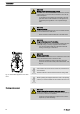
To check the pressure conditions in the piping system it is
recommended that connecting options are provided for a
manometer close to the suction and pressure connector.
1 Manometer socket
2 Discharge line (pipe)
3 Discharge valve
4 Suction valve
5 Suction line (pipe)
CAUTION!
Connect the pipelines to the pump so that no residual forces
act on the pump, e.g. due to the offsetting, weight or expan‐
sion of the line.
Only connect steel or stainless steel piping via a flexible
piping section to a plastic liquid end.
1 Steel pipeline
2 Flexible pipe section
3 Plastic liquid end
CAUTION!
Danger due to incorrect use of the integral relief valve
The integral relief valve can only protect the motor and the
gear, and then only against impermissible positive pressure
that is caused by the metering pump itself. It cannot protect
the system against positive pressure.
– Protect the motor and gear of the system against posi‐
tive pressure using other mechanisms.
– Protect the system against illegal positive pressure using
other mechanisms.
1
1
2
3
4
5
P_MOZ_0020_SW
Fig. 17: Manometer connecting options
1
2
3
P_MOZ_0021_SW
Fig. 18: Steel pipeline at the liquid end
Integral relief valve
Installation
25