
Operating instructions


CAUTION!
Warning of feed chemical spraying around
If no relief valve was connected to the overflow line, the feed
chemical sprays out of the hose connection as soon as the
relief valve opens.
– An overflow line must always be connected to the inte‐
gral relief valve and be fed back to the storage tank or -
if required by the regulations - into a special storage
tank.
CAUTION!
Danger of cracking
Cracking of the PVT liquid end can occur if a metal overflow
line is connected to the relief valve.
– Never connect a metal overflow line to the relief valve.
CAUTION!
Danger of the integral relief valve failing
The integral relief valve no longer operates reliably with feed
chemicals having a viscosity of greater than 200 mPa s.
– Only use the integral relief valve with feed chemicals
having a viscosity up to 200 mPa s.
CAUTION!
Warning against leaks
Feed chemical which remains in the overflow line at the relief
valve, can attack the valve or cause it to leak
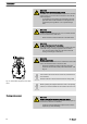
– Route the overflow line with a continuous slope and
moreover with the tube nozzle pointed downwards - see
Fig. 19.
If the overflow line is fed into the suction line, the bleed func‐
tion is blocked.
Therefore lead the overflow line back into the storage tank.
When operating the integral relief valve close to the opening
pressure, a minimal overflow into the overflow line can occur.
CAUTION!
Danger resulting from unnoticed diaphragm rupture
If the pump has been ordered with an electric diaphragm rup‐
ture sensor, it still has to be installed.
– Screw the enclosed diaphragm rupture sensor into the
liquid end (no seal necessary).
P_SI_0023
Fig. 19: Permissible alignment of the relief
valve
Diaphragm rupture sensor
Installation
26