
Operating instructions


For technical data see "Technical Data" chapter.
1. Install the cable which originates from the pacing relay - see the
figure in the chapter entitled "Overview of equipment and control
elements": Cable A, left.
The cable polarity is unimportant.
2. Install the power supply cable to the pacing relay PCB - see the
figure in the chapter entitled "Overview of equipment and control
elements": Cable B, right.
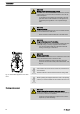
CAUTION!
Warning of overload
If the current through the relay becomes too high, both
it and the pump could be destroyed by overheating.
– Fit a circuit breaker.
The contacts are potential-free.
As a NC fault indicating relay the relay closes immediately after the power
is switched on and opens in the event of a fault.
As a N/O fault indicating relay, the relay closes in the event of a fault.
Use suitable interference suppression (e.g. RC members) when con‐
necting inductive loads.
Data Value Unit
Maximum voltage 250 VDC
(50/60 Hz)
Maximum current 2 A (resis‐
tive)
Closing duration -
Service life * > 200 000 Play
* at rated load
Behaviour: - see identity code
The contacts are potential-free.
Pin assignment
Pacing relay (option)
Relay technical data
Fault indicating relay
2
3
1
4
P_SI_0010_SW
Fig. 20: Pump pin assignments
Fault indicating relay
P_SI_0043
Installation
28