
Operating instructions


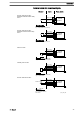


Wiring diagramWiring diagram
View of the cable plug from the front
Level switch cable
Dosing monitor cable
Diaphragm rupture sensor cable
Universal control wire (5-core)
External/contact cable (2-core)
3
2
1
3 brown / Stop
2 blue / Alarm
1 black / GND
1
4
2
3
1 brown / 5 V
2 white / Cod.
4 black / GND
3 blue
2
1
2 blue / Alarm
1 black / GND
4 white
2 brown
4
2
1 brown / Stop
2 white / Contact
4 black / GND
3 blue / Analog +
5 grey /Auxiliary
1
4
2
3
5
for
for
for
for
for
blue + black: open
-> Alarm message
brown + black: open
-> Alarm message + Pump stopped
Contact open -> Alarm message +
For control type 0: Pump stopped
Close contact -> Metering stroke
Pause function:
brown + black: closed
-> Pump dosing
brown + black: open
-> Pump stopped
External/Contact:
white + black: close
-> Start contact for pump
Analog:
blue, black
-> Analog input 0/4-20 mA
(Pause function inactive?:
brown + black: closed)
(Pause function inactive?:
brown + black: closed)
Auxiliary rate:
grey + black: closed
-> Pump dosing with preset
stroke rate
Wiring example - see next page
P_SI_0090_SW
External control
Installation
31