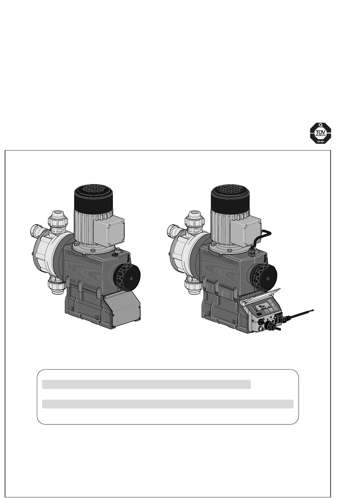
ProMinent ® Operating Instructions ProMinent® Sigma/ 2 S2Ba (Basic Type) S2Ca (Control Type) STOP START S2Ba S2Ca S2Ba ___ ___ ___ ___ ___ ___ ___ ___ ___ ___ ___ ___ S2Ca ___ ___ ___ ___ ___ ___ ___ ___ ___ ___ ___ ___ ___ ___ ___ Please enter the identity code of the device here.
Control elements and key functions Control elements: overview 4 3 2 1 5 16 6 7 8 9 10 15 14 13 12 11 1 2 3 4 5 6 7 8 9 10 11 12 13 14 15 16 Operating light (green) Warning light (yellow) Error warning light (red) Stroke length adjuster LCD display UP key DOWN key P key STOP/START key i key Relay output (optional) Metering monitor socket Float switch socket External control socket Diaphragm rupture indicator socket Mains switch Key functions In continuous display mode (operating) In settings mode (
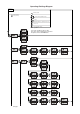
Operating-/Settings Diagram Continuous display Start/stop pump STOP START 1 = Lock (CODE 1) 2 = Lock (CODE 2) 2 Change directly alterable values Prime P P Start batch (in"batch" operating mode only) Cancel error Check adjustable values i p. 52 Analog P 2s 1 mode Select the operating mode here first, then carry out the settings in the SET menu. mode Exceptions: Timer and PROFIBUS®. Manual mode Analog Manual Contact Batch P mode p. 44 mode none code P Contact code1 P p.
previous page p. 49 p. 49 p. 50 Calib Set Set Set P Set Set p. 34 p. 51 p. 51 p.
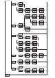
& Stop Analog Stop Analog Stop Analog $# i i ANJ i mA % i !$& !$& $# Stop Manual i Stop Manual i Stop Analog i L !#$ Stop Manual !#$ Stop Analog i i N %# L /h Stop Manual %# Stop Analog i & Stop Manual L N L /h Freq. % i Operating mode "Manual" i Stop Analog Freq.
Dulcodes UV-Desinfektionsanlage Imprint Imprint Operating Instructions for ProMinent® Sigma/ 2 S2Ba/S2Ca © ProMinent Dosiertechnik GmbH, 2002 ProMinent Dosiertechnik GmbH Im Schuhmachergewann 5-11 69123 Heidelberg · Germany info@prominent.de www.prominent.de Subject to technical modifications.
Dulcodes UV-Desinfektionsanlage Table of contents Page Device Identification/Identcode ® ProMinent 9 1 Notes on safety of ProMinent ® metering pumps 11 1.1 Summary of additional safety instructions for the EX version of the pump (in accordance with ATEX) 11 1.2 General notes 13 1.3 Notes on installation, start-up and operation 13 1.4 Notes on maintenance and repair 14 2 Product description S2Ba/S2Ca 15 2.1 Identification of pump type 15 2.2 Design/Functional description 15 2.2.
Dulcodes UV-Desinfektionsanlage Table of contents 6 Control elements 42 7 Settings 43 7.1. Check adjustable values 44 7.2 Change to settings mode 44 7.3 Select operating mode (MODE menu) 44 7.4 Settings for operating mode (SET menu) 45 7.4.1 Settings for “manual” operating mode 45 7.4.2 Settings for “analogue” operating mode (ANALG menu) 45 7.4.3 Settings for “contact” operating mode (CONTCT menu) 47 7.4.4 Settings for “batch” operating mode (BATCH menu) 49 7.
Dulcodes UV-Desinfektionsanlage Identcode ordering system Identcode ordering system Please enter the identcode on the device label into the grey box below.
Dulcodes UV-Desinfektionsanlage Identcode ordering system Identcode ordering system Please enter the identcode on the device label into the grey box below.
Dulcodes UV-Desinfektionsanlage 1 Notes on safety of ProMinent ® metering pumps Notes on safety of ProMinent ® metering pumps General user instructions Please read through the following user instructions carefully! They will help you get the best use out of the operating instruction manual. The following are highlighted in the text: • Enumerations 왘 Instructions Operating guidelines: NOTE Notices are intended to make your work easier.
Notes on safety of ProMinent ® metering pumps Dulcodes UV-Desinfektionsanlage • Installations in potentially explosive atmospheres must be inspected by an “accredited qualified” person. This applies in particular also for intrinsically safe electrical circuits. • Drive motors must be secured by an appropriate motor protection switch. A motor protection approved for this application must be used for Ex“e”-motors. (Protection against heating due to overload) • Observe all relevant standards e.g.
Dulcodes UV-Desinfektionsanlage Notes on safety of ProMinent ® metering pumps Safety devices The following safety notice must be affixed to the pump (with PP, PC and PV liquid ends, acrylic glass cover, ...
Notes on safety of ProMinent ® metering pumps Dulcodes UV-Desinfektionsanlage IMPORTANT • Set stroke length only with pump in operation! • Pull the red plug for venting the gear unit during initial operation of the Sigma/ 2 metering pump (refer to Fig.
Dulcodes UV-Desinfektionsanlage 2 Product description S2Ba/S2Ca Product description S2Ba/S2Ca WARNING Use for intended purpose • The pump is designed as a liquid medium metering pump; it serves the purpose of metering liquid medium within the specified line system! • In explosion-threatened workplaces in zone 1, device category II 2G of explosion group II C the pump may not be operated without the corresponding rating plate (and the corresponding EC conformity declaration) for pumps for explosion-threat
Dulcodes UV-Desinfektionsanlage Product description S2Ba/S2Ca 1 5 4 10 3 8 7 6 Fig. 2 61_01-101_00_25-01 2.2.2 Stroke movement a) Stroke progression at max. stroke rate and stroke length b) At reduced stroke length Stroke speed + Delivery stroke – Intake stroke 0 180 360 Angle reduced stroke length Fig. 3 Set stroke length dependent on the required delivery capacity. 30 % 30% 75 % 75% 0 50 25 75 20 0 0 25 5 0 5 10 Fig.
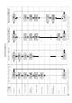
ProMinent ® 0 50 100 150 200 250 300 350 400 450 0 50 100 150 200 250 300 350 400 0 0 2 20 Stroke length in (%) 60 80 4 8 pressure in (bar) 6 10 Metering capacity diagram S2Ba HM (50 Hz) 40 S2Ba HM 12050 S2Ba HM 12090 S2Ba HM 12130 S2Ba HM 07120 S2Ba HM 07220 S2Ba HM 04350 Metering capacity diagram S2Ba HM (50 Hz) 12 S2Ba HM 12050 S2Ba HM 12090 S2Ba HM 12130 S2Ba HM 07120 S2Ba HM 07220 S2Ba HM 04350 100 14 120 Q (l/h) Q (l/h) 450 0 50 100 150 200 250
Page 18 Q (l/h) Q (l/h) 0 50 100 150 200 250 300 350 400 450 0 50 100 150 200 250 300 350 400 450 0 0 2 20 4 Stroke length in (%) 60 80 6 pressure in (bar) 8 10 Metering capacity diagram S2Ca HM 40 S2Ca HM 12050 S2Ca HM 07120 S2Ca HM 12090 S2Ca HM 07220 S2Ca HM 12130 S2Ca HM 04350 Metering capacity diagram S2Ca HM 12 14 S2Ca HM 12050 S2Ca HM 12090 S2Ca HM 12130 S2Ca HM 07120 S2Ca HM 07220 S2Ca HM 04350 100 16 120 Product description S2Ba/S2Ca Dulcodes UV-
Dulcodes UV-Desinfektionsanlage 2.2.4 Product description S2Ba/S2Ca Functional description, delivery unit The heart of the delivery unit is the DEVELOPAN® metering diaphragm (2). It hermetically seals the delivery chamber of the liquid end (4) and produces a displacement in the liquid end. The end disc (5) made of chemically resistant plastic together with safety diaphragm (13) separates the drive housing from the delivery unit and protects the drive from corrosion in the event of the diaphragm failing.
Dulcodes UV-Desinfektionsanlage Product description S2Ba/S2Ca 2.2.5 Integrated overflow valve with bleeder function Task: The task of the overflow valve is to protect the motor and gear unit against impermissible overpressure caused by the metering pump. This function is produced by a spring-loaded ball. A pressure relief mechanism for the bleeder function is provided. Design and functional description (refer to Fig. No.
Dulcodes UV-Desinfektionsanlage Product description S2Ba/S2Ca 134 102 133 132 138 111 137 112 139* 100 129 110 126 200 140 201 141 125 117 101 136 127 113 116 114 128 130 115 118 131 202 203 Overflow valve Sigma/ 2 liquid end, 16 bar SST Identcode Type: 16050, 16090, 16130 Overflow valve Sigma/ 2 liquid end, 12 bar SST Identcode Type: 12050, 12090, 12130 Overflow valve Sigma/ 2 liquid end, 7 bar SST Identcode Type: 07120, 07220 Overflow valve Sigma/ 2 liquid end, 4 bar SST Identco
Dulcodes UV-Desinfektionsanlage Product description S2Ba/S2Ca Technical data Corresponding to the type of pump, overflow valves are available for pressure stages pnom 4, 7, 10, 12 and 16 bar with (1.05 ... 1.15) xpnom opening pressure. Material in contact with metered medium Material version Liquid end Suction/ discharge connector Seals Balls Springs Integrated overload valve PVT PVDF PVDF PTFE Ceramic / glass* Hastelloy C PDFE/Viton® SST Stainless steel 1.4571/1.4404 Stainless steel 1.
Dulcodes UV-Desinfektionsanlage Product description S2Ba/S2Ca The liquid end can continue to operate in emergency mode, i.e. full operating pressure, no leakage, even after diaphragm rupture, until the diaphragm has been replaced. We offer two versions of the S3Ca with diaphragm rupture sensor: • After a working diaphragm rupture, the pump stops and an ”error“ message/diaphragm sensor signal is given. • After a working diaphragm rupture, the pump will continue to run.
Dulcodes UV-Desinfektionsanlage Product description S2Ba/S2Ca Material in contact with metered medium Liquid end: Parts of diaphragm failure monitor in contact with medium PVDF Stainless steel 1.4571 Lens, seals Item 148, 156, 159 Intermediate disc Item 147, intermediate bush Item 150 PTFE PTFE PVDF PVDF Electrical data for the diaphragm breakage sensor a) Switch contact 30 V DC/1 A or 125 V AC/0.6 A or 250 V AC/0.3 A The diaphragm sensor is a N/C relay.
Dulcodes UV-Desinfektionsanlage Technical data 3 Technical data 3.1 3.1.1 Technical data Sigma/ 2 Capacity data Technical data S2Ba at 50 Hz operation Feed rate at maximum back pressure Pump type Sigma/ bar l/h Max. stroke rate Suction lift Admissible priming pressure suction side Connection suction / discharge side Shipping weight ml/stroke strokes/min. m Ws bar G - DN kg 12050 PVT 10 50 11.4 73 7 3 1"-15 15 12050 SST 12 48 11.4 73 7 3 1"-15 20 16050 SST 16 48 11.
Dulcodes UV-Desinfektionsanlage Technical data Technical data S2Ca Feed rate at maximum back pressure Max. stroke rate Suction lift Admissible priming pressure suction side Connection suction / discharge side Shipping weight Pump type Sigma/ bar l/h ml/stroke strokes/min.
Dulcodes UV-Desinfektionsanlage 3.1.2 Technical data Dimensions Sigma/ 2 (mm) Connection variations 456/441* C A B PVDF ØG Ø165 185/170* PP/PVC/PTFE SS D/Dl 136 26.5 Ø 6.5 28 120 +7 120 F 79.5 222 Fig.
Dulcodes UV-Desinfektionsanlage Technical data 3.1.4 Motor data Electrical Data Motors: Identcode characteristic 3 ph IP 55 230 V/400 V 50 Hz 0.25 kW 1.62/0.94 A S 3 ph IP 55 230 V/400 V 60 Hz 0.25 kW 1.42/0.82 A S 1 ph AC 230 V 50/60 Hz 0.18 kW 1.7/1.5 A M 1 ph AC 115 V 60 Hz 0.18 kW 3.3 A N 3 ph EXe or EXde 230 V/400 V 50 Hz 0.18 kW 1.1/0.7 A L 3 ph EXe or EXde 230 V/400 V 60 Hz 0.18 kW 1.1/0.6 A P 3 ph IP 55 230 V/400 V 50/60 Hz 0.37 kW ......
Dulcodes UV-Desinfektionsanlage Technical data b) Namur sensor, intrinsically (Identcode characteristic “Stroke sensor”: 3) WARNING • EX-pump only: intrinsically safe installations must be installed and checked by persons with “recognised skills”! • EX-pump only: observe documents supplied with the sensor! Blue - Brown + 5-25 V DC, Namur type and/or DIN 19234, zero volt design.
Dulcodes UV-Desinfektionsanlage Start-up/Maintenance 4 Start-up/Maintenance WARNING • For all metering pumps for metering inflammable media applies: Starting up and emptying only supervised by a competent person. IMPORTANT Observe the safety notes provided in Section 1. 4.1 Start-up All general guidelines in the accompanying ”General operating instructions ProMinent® motordriven metering pumps and hydraulic accessories” apply.
Dulcodes UV-Desinfektionsanlage Start-up/Maintenance Maintenance intervals General recommendation for maintenance intervals - every 3 months. Shorter intervals are recommended if operated under load conditions (e.g. continuous operation). The gear oil should be changed after approx. 5000 duty hours. Gear oil ISO viscosity class VG 460, e.g. Mobil Gear 634, ProMinent Order No. 555325 (Amount of oil approx. 0.5 l).
Dulcodes UV-Desinfektionsanlage Start-up/Maintenance NOTE The tightening torque of the liquid end screws should be rechecked after 24 hours of operation. The tightening torques of the liquid end screws should be checked every 3 months for the PVT material version. Fig. 12 GUIDELINE ON VALVE INSTALLATION In the case of suction problems during installation, place the valves on a firm surface and tap the PTFE ball seat disk lightly with a brass rod and a hammer weighing about 300 g.
Dulcodes UV-Desinfektionsanlage Features of the S2Ca metering pumps 5 Features of the S2Ca metering pumps 5.1 Function description, motors The pump has an integrated electronic overload cut-out in all versions. This responds as soon as the maximum admissible power consumption is reached and stops the motor. 왘 If the motor stops due to a system overload the electronic controller detects the fault and transmits a message which is displayed on the display panel and at the pump.
Features of the S2Ca metering pumps Dulcodes UV-Desinfektionsanlage “PROFIBUS®” mode: (Identity code, control variant: PROFIBUS®) This operating mode provides the option of controlling the pump via the PROFIBUS® (see “Supplementary instructions for ProMinent® gamma/ L and ProMinent® Sigma versions with “PROFIBUS®”).
Dulcodes UV-Desinfektionsanlage Features of the S2Ca metering pumps Hierarchy of operating modes, functions and fault statuses The different operating modes, functions and fault statuses each have a differing effect on whether and how the S2Ca functions. These effects are given below: 1. Prime 2. Fault, stop, pause 3. Auxiliary frequency 4. Manual, analogue, contact, batch i.e. 1. “Prime” can be activated in “Stroke rate” permanent display in any pump status (as long as it is operable) 2.
Dulcodes UV-Desinfektionsanlage Features of the S2Ca metering pumps Technical data, relay (control version) 2 Pump type S2Ca 3 1 4 Relay Fault-indicating relay Relay type Fault-indicating relay Voltage, max: 250 V 50/60 Hz 24 V DC 24 V 50/60 Hz Current, max.
Dulcodes UV-Desinfektionsanlage Features of the S2Ca metering pumps Wiring diagram View of cable connectors from front Universal signal cable (5-core) 5 grey/auxiliary 4 black/ GND 1 brown / pause Blue and black open -> alarm signal Brown and black open -> alarm signal + pump stops 3 blue / analogue for 3 brown pause 2 blue/alarm 1 black GND for 2 white/cod Float switch cable Pause function: brown and black closed -> pump metering Metering monitor cable brown and black open -> alarm + pump
Dulcodes UV-Desinfektionsanlage Features of the S2Ca metering pumps Technical data, external contact Semi-conductor switch elements (e.g. transistors in open-collector circuits) or contactors (relays) with a residual voltage of -0.7 V can be used as input switch elements. Controller type 0 (see identity code) Pin 1 = Pause input (activating function) Voltage at open contacts: approx. 5 V Input resistance: 10 kΩ Controller: – zero volts contact (approx. 0.5 mA) – semi-conductor (residual voltage: < 0.
Dulcodes UV-Desinfektionsanlage Features of the S2Ca metering pumps Block circuit diagram S2Ca Inputs Empty signal, warning Outputs Pump, Inside 3 brown/pause 2 blue/alarm Level monitor 1 black/GND Fault indicating relay 1 brown/5 V 2 white/cod Metering monitor Flow control 3 blue Metering monitor 4 black/GND Diaphragm rupture sensor 2 blue/alarm 1 black/GND VDE cable: 2 green/NC 1 white /NO 4 brown/C VDE cable: 1 yellow/NO (fault) Fault indicating and pacing relay Diaphragm rupture sensor
Dulcodes UV-Desinfektionsanlage Features of the S2Ca metering pumps Circuit examples: universal signal cable by customer “External contact“ function (ProMinent® external/contact cable) two-core Cable Pump, inside 2 white/contact 4 brown/GND External activation Pulse rate, e.g. contact water meter “External contact“ function (ProMinent® universal signal cable) five-core 3 blue/analogue 2 white/contact 1 brown/pause 4 black/GND External activation 5 grey/auxiliary Pulse rate, e.g.
Dulcodes UV-Desinfektionsanlage Features of the S2Ca metering pumps IMPORTANT • The universal signal cable, the external/contact cable and the level monitor cable should not be less than 1.20 m long, otherwise cable recognition will fail. 5.
Features of the S2Ca metering pumps / Control elements Dulcodes UV-Desinfektionsanlage Fig. 17 6 Fig. 18 Control elements Please acquaint yourself with the S2Ca control elements with the help of the “control elements and key functions” overview! Indicators The LCD display supports the operation and setting of the S2Ca with a range of indicators: Stop Aux Pause Error Mem Calib Flow Set The indicators are interpreted as follows: Symbol for P key: The S2Ca is in settings mode.
Dulcodes UV-Desinfektionsanlage 7 Settings Settings NOTE • Open out the fold-out page following the title page fully! There you will find the overviews “control elements and key functions” and “operating settings diagram”. • If no keys are pressed within a period of 1 minute, the S2Ca will return to a continuous display.
Dulcodes UV-Desinfektionsanlage Settings 7.1 Check adjustable values Before setting up the S2Ca you can check the current settings of adjustable values: Press the i key (“i” as in “info”) when the S2Ca is in continuous display mode (There is no P key symbol in the LCD display). Each time you press the i key you will see a different continuous display.
Dulcodes UV-Desinfektionsanlage Settings • Contact: for contact operation (Identity code, control variant: external 1:1 / external with pulse control) • Batch: for batch operation (Identity code, control variant: external with pulse control) Analog - ANALOG Manual Analog Manual Contact Batch - MANUAL P P Contact - CONTACT Batch 7.4 - BATCH Settings for operating mode (SET menu) NOTE First select the operating mode in the MODE menu! Exceptions: Timer and PROFIBUS®.
Dulcodes UV-Desinfektionsanlage Settings • 4 - 20 mA: at 4 mA the S2Ca does not operate at 20 mA the S2Ca operates at 180 strokes/min. Between these two extremes the stroke rate is proportional to the electrical signal. For signals of below 3.8 mA a fault will be detected and the S2Ca will stop (e.g. cable break). • Curve: In the “curve” processing mode you can programme the S2Ca ratios.
Dulcodes UV-Desinfektionsanlage Settings Lower/upper band: This processing mode allows you to control a pump via an electrical signal as shown in the diagrams below. Lower band Upper band e.g. Alkali pump e.g. acid pump Fmax Fmax P1 F1 P2 F2 P2 F2 P1 F1 0 I1 Fig. 20 I2 20 I [mA] 0 I1 I2 I [mA] 20 Fig. 21 Lower band: The symbol appears in the LCD display. The S2Ca will operate below I1 at F1. Above I2, the S2Ca ceases to operate.
Dulcodes UV-Desinfektionsanlage Settings In the “contact - identity code: external with external pulse control” you can enter the number of pulses after which a stroke should be carried out. “Contact - identity code: external with external pulse control” is intended for small dosing quantities. set P Set cntct P Mem Set on Contact P Mem Set 0120 Contact P Continuous display The number of strokes per pulse depends upon the factor, which you can enter.
Dulcodes UV-Desinfektionsanlage Settings NOTE If a remainder occurs when the factor is processed, the S2Ca counts up the remainder values. When the sum reaches or exceeds “1” the S2Ca will activate a stroke. This ensures that the stroke number corresponds exactly to the factor throughout the dosing operation. The number of input pulses which have not been processed are stored by the S2Ca in the stroke memory.
Dulcodes UV-Desinfektionsanlage Settings 7.5 Settings for programmable functions (SET menu) The following programmable function settings menus appear in all operating modes: • Calibrate (CALIB menu) • Auxiliary frequency (AUX menu) • Flow (FLOW menu, available only if flow monitor is connected) 7.5.
Dulcodes UV-Desinfektionsanlage 7.5.2 Settings Settings for “auxiliary frequency” function (AUX menu) Aux IAJ P Set =KN P Set &# Freq. P Continuous display The programmable function “auxiliary frequency” allows switching to a different stroke frequency, which can be set in the AUX menu. It can be activated via the “external control” terminal. When the auxiliary frequency is activated, “aux” appears in the LCD display.
Dulcodes UV-Desinfektionsanlage Operating 8 Operating This section describes all operating options available to you when the S2Ca is in continuous display mode (no P key symbol in the LCD display). WARNING • For all metering pumps for metering inflammable media applies: Starting up and emptying only supervised by a competent person. NOTE • Open out the fold-out page following the title page fully! There you will find the overviews “control elements and key functions” and “operating/settings diagram”.
Dulcodes UV-Desinfektionsanlage Batch size Priming Cancel error Operating / Troubleshooting In “batch” operating mode: The batch size can by changed from the “batch size/remaining litres” display. The S3Ca returns to the original continuous display a few seconds after the batch size has been reset. The “priming” function is activated by pressing both arrow keys at the same time (in “Stroke rate” permanent display). Error messages are cancelled by pressing the P key briefly.
Dulcodes UV-Desinfektionsanlage Troubleshooting Green LED indicator (operating display) is not lit Cause Remedy Incorrect or no mains voltage. 왘 Use the recommended mains voltage as given in the voltage specification on the nameplate. Error Messages Red LED display is lit, “Error” and “MINIM” flash in the display Cause Remedy Fluid level in the chemical storage tank has reached “liquid level low, stage 2”. 왘 Fill the chemical supply container.
Dulcodes UV-Desinfektionsanlage Troubleshooting / Decommissioning and disposal Red LED display is lit, “Error” appears in the display and “FAN” is flashing Cause Remedy Fault related to fan in pump housing. 왘 Check fan and replace if necessary. 왘 Press the P key (reset function). Red LED display is lit, “Error” appears in the display and “SYSTEM” is flashing Cause Remedy Controller fault. 왘 Disconnect the pump from the mains and reconnect.
Dulcodes UV-Desinfektionsanlage Spare parts and accessories 11 Spare parts and accessories CAUTION The assembly and installation of ProMinent® metering pumps with other-make parts that are not tested and recommended by ProMinent are not permitted and can lead to personal injury and damage to property for which no liability shall be accepted! Spare parts You will find the order numbers for the wearing parts in the exploded view drawings in the annex.
Dulcodes UV-Desinfektionsanlage Motor data sheet Motor Datenblatt / Motor data sheet / Fiche technique pour moteur Bestell Nr. order no. / no. de commande 1011036 Motor-Typ motor type type du moteur AF 63/4C-7 Leistungsfaktor power factor facteur de puissance 0,66 Maschinenart type of machine désignation 3-Ph.
EC Declaration of Conformity Dulcodes UV-Desinfektionsanlage For pumps without Ex protection: For pumps with Ex protection: the EC conformity declaration for the pump for explosion-threatened workplaces is supplied with the pump. The EC conformity declarations, the EC series prototype test reports and the operating manuals for the individual components are also supplied with the pump.
Dulcodes UV-Desinfektionsanlage Exploded diagrams of liquid ends Delivery unit Sigma/ 2 350-DN 25 PVT for identity code types: S2Ba/S2Ca 04350, 07120, 07220 Delivery unit Sigma/ 2 130-DN 15 PVT for identity code types: S2Ba/S2Ca 12050, 12090, 12130 Valve assy DN 15/PVT* Order No. 792517 Valve spring * Valve ball * Diaphragm FM 120 Order No. 1010285 Ball seat * Valve assy DN 15/PVT* Order No. 792517 Spare parts kit FM 350 PVT Order No. 740325 Spare parts kit FM 130 PVT Order No.
Exploded diagrams of liquid ends Dulcodes UV-Desinfektionsanlage Delivery unit Sigma/ 2 350-DN 25 PVT for identity code types: S2Ba/S2Ca 04350, 07120, 07220 Delivery unit Sigma/ 2 130-DN 15 PVT for identity code types: S2Ba/S2Ca 12050, 12090, 12130 Overflow valve assy 12 bar PVA Order No. 1018572 Overflow valve assy 10 bar PVA Order No. 1018947 Overflow valve assy 7 bar PVA Order No. 740811 Overflow valve assy 4 bar PVA Order No.
Dulcodes UV-Desinfektionsanlage Exploded diagrams of liquid ends Delivery unit Sigma/ 2 350-DN 25 SST for identity code types: S2Ba/S2Ca 04350, 07120, 07220 Delivery unit Sigma/ 2 130-DN 15 SST for identity code types: S2Ba/S2Ca 12050, 12090, 12130 Spring ** Valve assy DN 10/SST* Order No. 809459 Ball * Diaphragm FM 050 Order No 1010279 Diaphragm FM 065 Order No. 1010282 Ball seat * Valve assy DN 10/SST* Order No.
Exploded diagrams of liquid ends Dulcodes UV-Desinfektionsanlage Retrofit kit double diaphragm S2Ba/S2Ca S1Ba Retrofit kit double diaphragm FM 050 Order No. 1009846 S1Ba Retrofit kit double diaphragm FM 065 Order No. 1009848 S1Ba Retrofit kit double diaphragm FM 120 Order No. 1009850 S1Ca Retrofit kit double diaphragm FM 050 Order No. 1009847 S1Ca Retrofit kit double diaphragm FM 065 Order No. 1009849 S1Ca Retrofit kit double diaphragm FM 120 Order No. 1009851 Lense Order No.
Dulcodes UV-Desinfektionsanlage Wiring diagram Stroke actuator wiring diagram Feedback signal mA Input signal mA 4 3 2 1 1 2 3 PE N L Power supply Wiring diagram for stroke length adjuster Power supply P2 P1 N 3 2 1 E V+ 5 Sig.