SQC-122c Thin Film Deposition Controller User’s Guide Version 2.0 © Copyright Sigma Instruments, Inc.
Safety Information Read this manual before installing, operating, or servicing equipment. Do not install substitute parts, or perform any unauthorized modification of the product. Return the product to Sigma Instruments for service and repair to ensure that safety features are maintained. Safety Symbols WARNING: Calls attention to a procedure, practice, or condition that could possibly cause bodily injury or death.
Warranty Information This Sigma Instruments product is warranted against defects in material and workmanship for a period of 1 year from the date of shipment, when used in accordance with the instructions in this manual. During the warranty period, Sigma Instruments will, at its option, either repair or replace products that prove to be defective.
Table of Contents Chapter 1 1.0 1.1 1.2 1.3 1.4 1.5 1.6 1.7 Introduction................................................................................................1-1 Thin Film Process Overview........................................................................1-1 System Connections...................................................................................1-2 Front Panel................................................................................................1-3 Rear Panel ..........
Appendix A. B. C. D. E.
Chapter 1 Quick Start 1.0 Introduction The SQC-122c is a multi-channel quartz crystal monitor and deposition controller. It measures up to six 1MHz to 6 MHz quartz crystal sensors, and controls two evaporation sources. Twenty-five processes, consisting of 250 layers and 25 materials, can be stored for easy retrieval. Eight process control relays, and eight digital inputs are easily configured to support a broad range of external functions, including source pocket rotation.
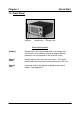
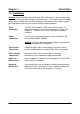
Chapter 1 Quick Start 1.2 Front Panel SoftKeys Control Knob Remote Jack Front Panel Controls SoftKeys Provide access to instrument operations and setup menus. The functions of the SoftKeys change to adapt to different operations and are displayed on the left of the screen. Control Knob Used to adjust values and select menu items. Pushing the control knob stores the current setting and moves to the next. Remote Jack Connection jack for the optional handheld remote control module. See Appendix D.
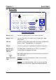
Chapter 1 Quick Start 1.3 Rear Panel ? Manufactured By Sigma SQC-122c Deposition Controller Serial No. instruments Sensor 3 Sensor 4 Output 3 Output 4 I/O 9-16 Sensor 1 Sensor 2 Output 1 Output 2 I/O 1-8 100-120/200-240 V~ 50/60 Hz 25 VA Fuse T.5A 250V RS-232 Rear Panel Connections Sensor 1 & 2 Connects to quartz crystal sensor remote oscillator. Output 1 & 2 Connects the SQC-122c output to your evaporation supply control input.
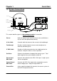
Chapter 1 Quick Start 1.4 System Connections Sensor In-Vac Cable Source Shutter Feedthrough BNC Cables 6" BNC Cable Oscillator Evaporation Supply Output Control Input Ground Wire This section identifies typical system components and their connection: System Components Sensor Holds the quartz crystal used to measure rate and thickness. Crystals must be replaced occasionally. In-Vac Cable A coaxial cable that connects the sensor to the feedthrough.
Chapter 1 Quick Start 1.5 Installation WARNING: Care should be exercised to route SQC-122c cables as far as practical from other cables that carry high voltages or generate noise. This includes other line voltage cables, wires to heaters that are SCR-controlled, and cables to source power supplies that may conduct high transient currents during arc down conditions. Rack Installation The SQC-122c occupies a 5.25” high, half-rack space.
Chapter 1 Quick Start 1.6 Process Setup Follow these steps to build a process from the main (also called “power up”) screen. Note: If you are prompted for a password, use the switches along the left of the screen to enter the password. The top switch is “1”, the bottom switch is “6”. If you forget the password, see the System Parameters section for password setup. Power On Move the rear panel power switch to the On (|) position.
Chapter 1 Edit Mode Quick Start To edit a setting in any menu, turn the control knob to scroll to the desired setting, then press the Edit SoftKey. In Edit mode, the cursor moves to the setting value and the SoftKey functions change to show: Next: Store the parameter and move to next parameter for editing. Cancel: Stop editing and return the selected parameter to its previous value. Enter: Stop editing and save values for selected parameter.
Chapter 1 Quick Start 1.7 Depositing a Film If you have followed this Quick Start chapter, you are ready to deposit a film. Note: You can simulate the steps below, without actually depositing a film, by going to the System Parameters Menu and selecting Simulate Mode ON. Simulate mode is useful for testing processes before applying power to the evaporation supply. See Section 3.6 for System Parameters Menu information. Verify Output Operation From the Main Menu, press the Next Menu SoftKey.
Chapter 1 Quick Start This page left blank for your notes.
Chapter 2 Operation 2.0 Introduction This chapter describes common tasks associated with operating the SQC-122c. It assumes that you understand basic operation of the menus and parameter setup as described in Chapter 1. Detailed definitions of unfamiliar setup parameters can be found under the appropriate menu description in Chapter 3. 2.1 Definitions Several terms will be used repeatedly throughout this manual. It is important that you understand each of these terms.
Chapter 2 Operation The most commonly modified parameters are shown on the first film parameters screen. Additional parameters can be accessed by pressing Film Conds (film conditioning) or Deposit Controls. Exit to Main Prev Menu Edit Film Conds. Deposit Controls THICKNESS(kA) 0.000 My Process 1 RATE(A/s) 0.0 POWER(%) 0.0 Editing: Aluminum Parameter Value Units P Term 50 None I Term 0.7 Sec. D Term 0.0 Sec.
Chapter 2 Operation The PID parameters control the response of the SQC-122c to changes in deposition rate. These values are unique to each deposition chamber setup, and to a lesser extent to each material. The P Term is proportional (or gain), the % process rate change divided by the % input power change. The I Term (integral) sums the rate deviations over time to more accurately achieve the rate setpoint. The D Term (derivative) speeds response to sudden changes in rate.
Chapter 2 Operation From the Film Conds menu, press Prev Menu to return to the main Film Params menu. Now press Deposit Controls. The Deposit Controls menu contains parameters that modify operation during the deposition phase. Exit to Main Prev Menu Edit THICKNESS(kA) 0.000 POWER(%) 0.0 RATE(A/s) 0.0 Current: Process 1 EDITING: Film 1 Parameter Value Units Shutter Delay 0:01:00 h:mm:ss Capture 20.0 % Control Error (Ignore, Stop, Hold) Setting Hold Error 18.
Chapter 2 Operation 2.3 Defining a Process A process is a sequence of film layers deposited to achieve a particular thin film characteristic. A few processes, each consisting of a few layers, may be adequate for a production facility. For research or laboratory use, the SQC-122c can store up to 25 processes to a total of 250 layers. You should define each of the films that will make up the layers of the process before starting process definition.
Chapter 2 Operation Initial Rate and Final Thickness are the main process setpoints for this layer of material. Keep in mind that the SQC-122c zeroes thickness at the beginning of each layer. It is not a cumulative value. Time Setpoint and Thickness Limit are arbitrary values that will activate a relay when they are reached. Start mode allows you to have this layer start immediately on completion of the previous layer, Auto mode.
Chapter 2 Operation 2.4 Sensor Setup The theory of operation for a quartz crystal sensor is quite simple. The sensor initially oscillates at its natural frequency, typically 6MHz. As material is deposited on the substrate, it is also deposited on the sensor. Depending on the density of the deposited material, and the amount of material deposited, the sensor’s frequency will drop from its initial frequency. The rate and thickness can be calculated from this frequency shift.
Chapter 2 Operation Sensor Tooling, also found in the System Params menu, adjusts for the difference in measured deposition rate between the sensor and the substrate being coated. Substrate Substrate Tooling Over 100% Tooling Under 100% In the illustration above (left), the sensor will measure less rate or thickness than is actually deposited on the substrate because of its positioning. In the right illustration, the sensor will measure high.
Chapter 2 Operation Once the sensor parameters are set, test your sensor setup to assure reliable readings at the SQC-122c. A typical single sensor setup is shown below: On the SQC-122c, press Next Menu until the Sensor Info option is shown, then press Sensor Info. Any connected sensor (whether programmed On or Off) should display its frequency and % remaining life, as defined by Min and Max Frequency setup. For a new sensor, the value should be near 100%. If the % Life is 0.
Chapter 2 Operation 2.5 Source Setup The SQC-122c controls deposition rate by varying the control voltage to an external evaporation (source) supply. The previous illustration for sensor wiring also shows source supply wiring. The SQC-122c control voltage output range is set in the Systems Params menu. For the supply connected to Output 1, set Scale 1 to the control voltage that corresponds to 100% output on the source supply.
Chapter 2 Operation 2.6 Running a Process Once a Process is defined with the desired Layers, and the sensors and source supply are properly connected, the deposition process is ready to run. The next section, on Loop Tuning, describes a method for initial process startup and optimization. This section describes the steps to select, start, and stop a process. Note: It is best (and safest!) to place the SQC-122c in Simulate mode when a process is first run.
Chapter 2 Operation While we’re on the Main Menu screen, and before starting the selected process, let’s cover the capabilities of the Next Menu screens. Press Next Menu once to view the first Next Menu screen. This screen provides two important operator functions: Zero Thickness and Auto/Manual mode. The Zero SoftKey can be used to zero the thickness reading at any time. It is not normally needed, since the SQC-122c automatically zeroes the thickness at the beginning of each layer.
Chapter 2 Operation Enough preliminaries, let’s start the process! Press Start from any of the main screen menus to start deposition. If the first layer Start mode was programmed as Manual, you will need to press the Start Layer SoftKey now to start the layer. Note: Don’t confuse Manual and Auto Start mode with the Manual/Auto SoftKey. Manual Start is a Process setup parameter that tells the SQC-122c to wait for operator intervention before starting a Layer. Next Menu THICKNESS(kA) 0.057 RATE(A/s) 0.
Chapter 2 Next Menu Operation THICKNESS(kA) 0.824 RATE(A/s) 7.8 POWER(% ) 55.3 100.0 Zero Auto / Manual Start Nxt Layer 50.0 0.0 0.0 40.0 Restart Layer Abort 80.0 120 Rate (A/s vs. Time) 160.0 PHASE: Stop Layer Process : My Process 1 Layer: 1 of 4 Run Time : 0:01:45 Final Thick : 1.100 Film : Film1 Layer Rate : 8.00 Layer Stopped Restart Layer repeats the stopped layer, beginning with preconditioning.
Chapter 2 Operation 2.7 Loop Tuning This section will help you adjust your control loop PID parameters to achieve a stable deposition process. Keep in mind that there is no “best” way to determine PID parameters, and no one set of settings that are “best.” Setup System Parameters: Be sure that the output Scale and crystal Min/Max Frequency parameters are accurate for your system. All Tooling parameters are best set to 100% for now. A Period of .25 seconds is also a good starting point.
Chapter 2 Operation about 10% overshoot, lower the P Term. If the time to reach PWRDR is very slow, increase the P Term. A lower I Term will increase response time, a higher value will eliminate ringing and setpoint deviations. It is unlikely you will need any D Term. Continue to Start the process and adjust PID until steady-state response is smooth and the step response is reasonably controlled.
Chapter 2 Operation 2.8 Troubleshooting Most SQC-122c problems are caused by defective crystals or improper film setup, particularly incorrect PID settings for the control loop. Follow the procedures below to identify and correct common problems. 2.8.1 No Readings, or Erratic Readings from Sensors: Disconnect the deposition source supply. This eliminates the possibility that a noisy source, or poor loop tuning, are causing an unstable PID loop.
Chapter 2 Operation When the frequency reading is stable, reconnect the source supply. Start the deposition process in Manual mode with 0% output. The % Life readings should remain stable. Slowly raise the % Output until a rate reading is displayed above the graph. As material is deposited on the crystal, the % Life reading should remain stable, or drop slowly and consistently. If not, check your source supply for erratic output.
Chapter 2 Operation This page left blank for your notes.
Chapter 3 Menus 3.0 Introduction SQC-122c operation during deposition is accomplished by pressing one of the six SoftKeys along the left of the display. Five menus provide access to all programmable and operating functions: Main Menu The Main Menu is displayed at power up. It provides the SoftKey functions and display information necessary to run a thin film deposition. On the Main Menu, you can view additional sub-menus by repeatedly pressing the Next Menu SoftKey.
Chapter 3 Menus 3.1 Main Menu The default, power-up Main Screen display is shown below. Next Menu THICKNESS(kA) 0.000 RATE(A/s) 0.0 POWER(% ) 0.0 100.0 Quick Setup Process Menu Film Menu 50.0 0.0 0.0 12.5 System Params Start 25.0 37.5 Power (% vs. Time) 50.0 PHASE: Stopped Process : My Process 1 Layer: 1 of 25 Run Time : 0:00:00 Final Thick : 0.1011 Film : Aluminum Layer Rate : 11.
Chapter 3 Menus The Main Screen SoftKeys undergo subtle changes based on the current process status. The table below describes the function of each of the possible SoftKeys on the Main Screen. Next Menu Displays additional Main Menu options as described in Section 3.2. Quick Setup Displays the Quick Setup Menu of commonly changed process values. Process Menu Create, delete, and edit up to 25 processes. Also used to select the currently active process.
Chapter 3 Menus 3.2 Next Menu Screens The Next Menu SoftKey provides access to two sub-menus of the Main Menu that control display and operating mode preferences. Next Menu THICKNESS(kA) 0.000 RATE(A/s) 0.0 POWER(%) 0.0 100.0 THICKNESS(kA) 0.000 50.0 0.0 0.0 POWER(%) 0.0 50.0 Switch Displays Sensor Info 12.5 25.0 37.5 Power (% vs. Time) 0.0 0.0 50.0 12.5 PHASE: Stopped Start RATE(A/s) 0.0 100.0 Next Graph Zero Auto / Manual Next Menu Run #: 1 5-16-00 50.
Chapter 3 Menus 3.3 Quick Setup Menu The Quick Setup Menu provides access to the most commonly adjusted parameters for the current process and layer. THICKNESS(kA) THICKNESS(kA) RATE(A/s) RATE(A/s) Main Exit to 0.000 0.00.0 0.000 THICKNESS(kA) RATE(A/s) Screen Main Exit to My Process 1 -> Layer 1 -> Aluminum 0.000 0.0 Main Scroll Processes with KnobValue Parameter Prev Menu Edit Edit Edit Prev Delete Layer Prev My Process 1 -> Layer 1-> Aluminum 1. My Process Init Rate 1 11.1 Parameter Value 2.
Chapter 3 Menus Quick Setup parameters are described below: Initial Rate: The beginning rate of deposition for this layer. Final Thickness: The desired final thickness of this layer. The deposition phase of this layer will end when this thickness is reached. P Term: Sets the gain of the control loop. High gains yield more responsive (but potentially unstable) loops. Try a value of 50, then gradually increase/decrease the value to respond to step changes in rate setpoint.
Chapter 3 Menus 3.4 Process Menus There are several tiers of Process Menus. The first menu (shown below) selects the current process. The current process is the process that is ready to run, and also the process that is selected for editing. Main Screen Prev Menu THICKNESS(kA) 0.000 RATE(A/s) 0.0 POWER(%) 0.0 My Process 1 -> Layer 1 -> Aluminum Scroll Processes with Knob 1. My Process 1 2. My Process 2 Edit 3. My Process 3 4. My Process 4 Delete 5. My Process 5 6. My Process 6 7. My Process 7 8.
Chapter 3 Menus The second Process Menu shows the sequence of layers that will be deposited in the current process. Main Screen Prev Menu THICKNESS(kA) 0.000 RATE(A/s) 0.0 POWER(%) 0.0 My Process 2 -> Layer 2 -> Aluminum Layer Film Layer 1 Aluminum Layer 2 AluminumOxide Edit Cut / Paste Insert Layer Layer Select Menu Main Screen Returns to the Main Menu. Prev Menu Returns to the Process Select Menu. Edit Displays the Layer Edit Menu for the highlighted layer (see next page).
Chapter 3 Menus Each layer consists of a film (i.e. a material), plus the deposition rate and thickness that are desired for this layer. The Layer Edit Menu provides access to these layer parameters: Exit to Main Prev Menu Edit THICKNESS(kA) 0.000 RATE(A/s) 0.0 POWER(%) 0.0 My Process 2 -> Layer 2 -> AluminumOxide Parameter Value Units Init Rate 9.9 A/s Fnl Thk 9.000 kA Time Setpoint 0:00:00 h:mm:ss Thickness Limit 0.000 A Start Mode Ramp 1 Manual Auto/Man.
Chapter 3 Menus A description of each parameter on the Layer Edit Menu follows: Initial Rate: The beginning rate of deposition for this layer. Final Thickness: The desired final thickness of this layer. The deposition phase of this layer will end when this thickness is reached. Time Setpoint: Sets an arbitrary time, after deposition begins, when the time setpoint relay is activated. Thickness Limit: Sets an arbitrary thickness when the thickness limit relay is activated.
Chapter 3 Menus 3.5 Film Menus Each film has certain characteristics that determine how it should be deposited. The Film Menus allow you to set parameters that regulate the deposition of each film in a certain process. Main Screen Prev Menu THICKNESS(kA) 0.000 My Process 1 RATE(A/s) 0.0 POWER(%) 0.0 Editing: Scroll Films with Knob 1. Film 1 2. Film 2 Edit 3. Film 3 4. Film 4 Delete 5. Film 5 6. Film 6 7. Film 7 8. Film 8 9. Film 9 10. Film 10 11.
Chapter 3 Menus The material to be deposited is the most significant film parameter. However, a film definition also includes the setup parameters shown below: Exit to Main Prev Menu Edit Film Conds. Deposit Controls THICKNESS(kA) 0.000 My Process 1 RATE(A/s) 0.0 POWER( %) 0.0 Editing: Aluminum Parameter Value Units P Term 50 None I Term 0.7 Sec. D Term 0.0 Sec. Sensor 1 On On/Off Sensor 2 On On/Off Film Tooling 100 % Output Out1 Out1/Out2 Pocket 1 Max Power 76.
Chapter 3 Menus The Film Conds SoftKey displays these additional film conditioning settings: (Refer to section 2.2 for definitions). Exit to Main Prev Menu Edit THICKNESS(kA) 0.000 My Process 1 RATE(A/s) 0.0 POWER(%) 0.0 Editing: Aluminum Parameter Value Units Ramp1 Power 50 % Ramp1 Time 0.7 h:mm:ss Soak1 Time 0.0 h:mm:ss Ramp2 Power On % Ramp2 Time On h:mm:ss Soak2 Time Out1 h:mm:ss Feed Power 75.0 % Ramp Time 10.0 h:mm:ss Feed Time 0:00:00 h:mm:ss 2.90 % 0.
Chapter 3 Menus The Deposit Controls SoftKey displays these additional film settings: (Refer to section 2.2 for deposition control definitions.) Exit to Main Prev Menu Edit THICKNESS(kA) 0.000 RATE(A/s) 0.0 Current: Process 1 POWER(%) 0.0 EDITING: Film 1 Parameter Value Units Shutter Delay 0:01:00 h:mm:ss Capture 20.0 % Control Error (Ignore, Stop, Hold) Setting Hold Error 18.0 Rate Sampling Setting % (Cont,Time,Acc based) Undefined Accuracy Based 0.
Chapter 3 Menus A description of each film parameter follows: P Term: The proportional term sets the gain of the control loop. High gains yield more responsive (but potentially unstable) loops. Try a value of 50, then gradually increase/decrease the value to respond to step changes in rate setpoint. I Term: The integral term controls the time constant of the loop response. A small I term, say .5 to 1 seconds, will smooth the response of most loops.
Chapter 3 0 1 2 3 4 Menus Disabled 30.0% 25.0% 20.0% 15.0% 5 6 7 8 9 12.5% 10.0% 7.5% 5.0% 2.5% Note: The Crystal Quality setting is very sensitive to PID loop tuning. It is best to leave Crystal Quality disabled until you are confident of your process and PID settings. Crystal Stability: As material is deposited on the crystal, the frequency normally decreases. However arcing, mode hopping, or external stresses may cause the crystal frequency to increase.
Chapter 3 Menus Feed: The feed phase holds output power at the level and time required to wire feed new material. Idle: Idle power ramps output power back to zero, or holds the material at a state that is ready for deposition (usually the same as Ramp 2 power). Shutter Delay: It is often desirable to obtain deposition control before the substrate shutter opens. Enabling shutter delay requires that the system reach a specific capture accuracy before the shutter opens.
Chapter 3 Menus 3.6 System Parameters Menu The System Parameters Menu contains settings that affect the basic operation of the SQC-122c. System parameters generally pertain to the physical setup of your vacuum system equipment. Exit to Main Edit I/O Setup THICKNESS(kA) 0.000 RATE(A/s) 0.0 POWER(%) 0.0 My Process 1 -> Layer 1 -> Aluminum Parameter Value Units Period System Tooling .25 Sec 100 % Xtal Tool 1 100 % Xtal Tool 2 Simulate Mode 100 Off % On/Off Min Frequency 5.
Chapter 3 Menus Descriptions of each System Parameter follows: Period: Sets the measurement period between .1 second (10 readings per second) and 1 second. A longer period gives higher reading accuracy, especially in low rate and low density applications. Period (seconds) .1 .25 .5 .75 1 Frequency Resolution (Hz) .3 .12 .06 .04 .03 System Tooling: Adjusts for overall sensor deposition rates that differ from the measured substrate deposition rate.
Chapter 3 Menus Rate Alarm Low: Sets the % deviation below rate setpoint that causes an audible alarm. Rate Alarm High: Sets the % deviation above rate setpoint that causes an audible alarm. The tone of the high rate alarm is lower than that of the low rate alarm. Password Enable: If Password is enabled, the Quick Start, Film and System Menus require a password. The Process Menu can be used to select a process, but a password is required to make any changes on the Process Menu.
Chapter 3 Menus 3.7 I/O Setup The I / O Setup SoftKey displays a menu allowing you to map the eight digital inputs and the eight digital outputs. Exit to Main Prev Menu Edit THICKNESS(kA) 0.000 RATE(A/s) 0.0 POWER(%) 0.0 My Process 1 -> Layer 1 -> Aluminum Parameter Value Input 1 None Input 2 None Input 3 None Input 4 None Input 5 None Input 6 None Input 7 None Input 8 None Relay 1 None Relay 2 None Relay 3 None I / O Mapping Menu Exit to Main Returns to the Main Menu.
Chapter 3 Menus In the I/O Setup Menu, any number of “events” can be mapped to the eight digital inputs and eight relay outputs. Options are set by selecting a relay or input and then turning the control knob to select the desired setting.
Chapter 3 Menus This page left blank for your notes.
Chapter 4 Options 4.0 Introduction This section covers the installation of optional accessories. 4.1 Option Card No option cards are available for the SQC-122c, although the rear panel has locations for an expansion card. To expand the SQC-122c, the unit can be upgraded to an SQC-222. Contact Sigma for information on this factory-only upgrade. 4.2 Full Rack Extender Installation The Full Rack Extender option (PN 900-007) mounts a single SQC-122c into a full width 19” rack space.
Appendix A.
Appendix B. Specifications Measurement Number of Sensors Frequency Range Frequency Accuracy Frequency Resolution Rate Accuracy Rate Resolution Thickness Accuracy Thickness Resolution Measurement Period Source Number of Sources Control Voltage Resolution Digital I/ O Digital Inputs Functions Input Rating Relay Outputs Functions Relay Rating General Specifications Mains Power Supply Power Consumption Operating & Transportation Environment Storage Environment Rack Dimensions (HxWxD) Weight 2 4.0 MHz to 6.
Appendix Display Graphs Readouts Process Parameters (a Process is a sequence of layers) # Processes # Films # Layers (total all processes) Layer Parameters (Layer is a Film, plus these values) Initial Rate Final Thickness Time Setpoint Thickness Limit Start Mode # Rate Ramps Rate Ramp Start Rate Ramp Time New Rate Film Parameters (Film is a Material, plus these values) Material Density Z-Factor P Term I Term D Term Sensor (1,2) Output Pocket Max Power Slew Rate Crystal Quality Crystal Stability Crystal Fail
Appendix C. I/O Connections A 25 pin D-sub connector, located on the rear of the SQC-122c, provides Input/Output connections. Refer to Section 3.6 for relay and input functional assignments. Inputs can be activated either by connecting to a switch and shorting to Ground, or they can be driven by a TTL compatible signal. WARNING: These are not isolated inputs! The voltage level applied must be limited to between 0 and +5 volts with respect to Ground.
Appendix A Y adapter cable can be used to provide compatibility with older (non color) models of the SQC-122, as shown below. Contact Sigma for information on purchasing this adapter, or other custom I/O cables.
Appendix D. Handheld Remote Controller The Handheld Controller provides the capability of adjusting output power remotely when the SQC-122c is in Manual Mode. ABORT ? Sigma instruments Handheld Controller To use the handheld controller, attach the cable from the handheld controller to the Remote jack on the SQC-122c front panel. Select a Process using the SQC-122c front panel SoftKeys. Press Next Menu until the Auto/Manual SoftKey is displayed.
Appendix E.