MicroObserver Unattended Ground Sensor System PRELIMINARY Users Manual Models M-100 & MO-1045 ITAR NOTICE This product and/or its technical data are export controlled by the U.S. State Department and covered by the International Traffic in Arms Regulations (ITAR). It may not be exported or transferred to any foreign person in the United States or abroad, except as authorized by the U.S. Department of State or the ITAR. Violators of these export laws are subject to severe civil and criminal penalties.
FCC Information Note: This equipment has been tested and found to comply with the limits for a Class A digital device, pursuant to Part 15 of the FCC. rules. These limits are designed to provide reasonable protection against harmful interference when the equipment is operated in a commercial environment. This equipment generates, uses, and can radiate radio frequency energy and, if not installed and used in accordance with the instruction manual, may cause harmful interference to radio communications.
Table of Contents 1 INTRODUCTION...................................................................................................................................... 4 2 NETWORK ARCHITECTURE............................................................................................................... 4 3 SYSTEM COMPONENTS........................................................................................................................ 6 4 SYSTEM OPERATION .......................................
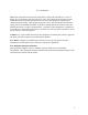
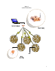
1 Introduction The MicroObserver system is designed to provide a user with an easy-to-use, robust, scalable wireless network that detects intruding persons and vehicles. The system may be used in applications such as military reconnaissance missions, situational awareness scenarios, or for perimeter security similar to industrial plant security and border protection. The system consists of a remote gateway and multiple nodes which interface with a usersupplied, user-interface display.
Figure 1 System Connectivity 5
3 System Components The MicroObserver system consists of two (2) primary pieces of hardware, the MicroObserver Sensor Node, MO-1045, and the Maestro Gateway, M-100. MicroObserver Sensor Nodes have two primary functions, to detect intruders and communicate with the network. The sensors employ seismic transducers to detect both dismounted personnel and vehicles (Vehicle Detection & Classification will be integrated in 2Q 2007).
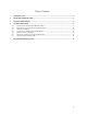
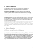
Figure 2 Inserting Battery Holder Into Node Once the batteries are installed the cover door is snapped shut, and the 4” stainless steel ground spike is installed by screwing it onto the bottom of the sensor. Hand tighten the spike to the sensor. Do not over tighten, and do not use a wrench. Ensure the spikes are firmly seated before placing the sensor in the ground. The sensor is activated by pushing the ON/OFF button located in a cut-out on the bottom of the unit as shown in Figure 3.
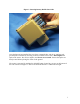
Figure 3 Node Turn On/Off • • • • To turn on the sensor, push and firmly hold the button for three (3) seconds. The LED light will illuminate a constant color. As a visual check to see if the unit is on, pushing the ON/OFF button for less than one (1) second will result in a steady LED indicator. To turn off the sensor, hold the button down for three (3) seconds. The LED indicator will display a steady light until the button is released.
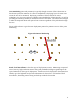
Area monitoring (Area and perimeter) is typically thought in terms of Force Protection or Fixed Asset protection missions. It is best accomplished by deploying layers of sensor rows across the area to be monitored. Deploying a number of sensors allows for sensor redundancy in a given area and gives a higher system Probability of Detection (Pd), as well as providing the necessary number of detections to form a valid track.
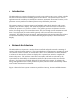
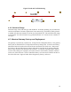
Figure 5 Road and Trail Monitoring 4.1.2 Detection Range Detection range varies with soil type and conditions. Generally speaking, clay is better than sand as a transmitter of seismic signals since loose material (e.g. leaf debris, freshly plowed or muddy soil) does not transmit as well as dry, hard packed soil. The stated detection range is 0-30 meters. We have measured very good performance at 7.5 meters across a number of soil types. 4.
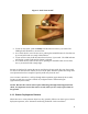
Figure 6 Gateway with Battery and Cover If not attached already, attach the 7.75” 5 dBi radio antenna to the marked “radio” antenna connector on side of the gateway. Attach the marked GPS antenna to the marked GPS antenna port on front of the gateway. Do not over tighten the connectors. The Maestro gateway is activated via a toggle switch located on the front of the unit. Turning the switch to the ON position will result in a red LED indicator on the front of the unit.
• • • • • • • • • • • On the computer, open Control Panel from the Windows Start Menu. Open Network and Internet connections Open Network Connections Right Click Local Area Connections Open Proprieties Using the pull down menu, locate and highlight Internet Protocol (TCP/IP) Click on Proprieties Select the button “Use the following IP address” Under IP address type in 192.168.1.1 Click on OK Click on Close. The control computer is now able to communicate with the gateway.
On the lower right corner of the GUI there is a Network State message displayed. The message may display the following circumstances: RESET: COALESCING OPERATIONAL UNKNOWN When the network is first brought up or the user has initiated a network reset using either the RESET or FORCED RESET commands When the network is forming When the network has formed and is operating in normal conditions The operator terminal has lost communication with the gateway.
4.7 Shutting Down the Network The network shut down procedure is: • • • 5 Turn off the gateway Close the operator terminal and shut down the computer Pick up and power off the nodes. Trouble Shooting Guide Network State Unknown With pre-production release hardware and GUI system, the network may occasionally go into Network State: Unknown status. This is a very infrequent condition that can be dealt with in the following manner. • • • • • Close the operator terminal program on the control computer.
• • Dead batteries. Physically dropping the sensors causes a momentary power interrupt. Power cycling the sensor will remedy this. Some or all of the Nodes do not join the network • In especially challenging RF conditions, there may be instances where not all of the sensors will join the network. The best solution at this point is to follow the reset & re-coalesce procedure listed in section 4.6 If any problem persists after following these instructions, call the factory for trouble shooting assistance.