
User's Manual


11
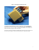
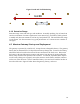
Figure 6 Gateway with Battery and Cover
If not attached already, attach the 7.75” 5 dBi radio antenna to the marked “radio” antenna
connector on side of the gateway. Attach the marked GPS antenna to the marked GPS
antenna port on front of the gateway. Do not over tighten the connectors.
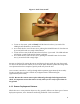
The Maestro gateway is activated via a toggle switch located on the front of the unit.
Turning the switch to the ON position will result in a red LED indicator on the front of the
unit. The gateway should acquire GPS coordinates in approximately 60 seconds.
Connection to the control terminal computer is accomplished via an Ethernet cross-over
cable or by a RS-232 serial cable [RS-232 is a future feature]. Both connections are clearly
marked on the front of the gateway. Once the GPS coordinates have been acquired, the
gateway is ready to operate.
4.3 Operator Terminal
Connect the Ethernet cross over (equipped with RJ45 connectors) to the appropriate port of
the control computer. Power up the computer as you normally would. Start the Operator
Terminal software. For the initial start up, the computer IP address will need to be set to
communicate with the gateway.