
User's Manual

6
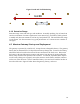
3 System Components
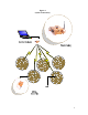
The MicroObserver system consists of two (2) primary pieces of hardware, the
MicroObserver Sensor Node, MO-1045, and the Maestro Gateway, M-100.
MicroObserver Sensor Nodes have two primary functions, to detect intruders and
communicate with the network. The sensors employ seismic transducers to detect both
dismounted personnel and vehicles (Vehicle Detection & Classification will be integrated in
2Q 2007). Seismic activity is measured and evaluated at the sensor with potential valid
detections sent to the hub via a 2.4 GHz wireless connection which then relays the
information wirelessly to the Maestro Gateway.
The Maestro Gateway is the wireless communications bridge between the sensor field and
the user’s C4I System. Potential detections received from the sensors are evaluated at the
gateway and, if validated, are passed to the C4I system via either Ethernet or RS-232 (RS-
232 will be integrated in the future).
Detections are validated at the Maestro Gateway through the use of a tracker. The tracker is
a unique software feature that, with correlated detections on 3 separate nodes, will form a
track indicating the direction, speed and time of a potential threat. When vehicle detection is
added in 2007 production, the threat will further be identified as either a person or a light or
heavy vehicle.
4
System Operation
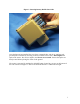
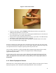
4.1 Sensor Start-up Procedure & Deployment
The MicroObserver sensors were designed for ease of set-up and deployment. The nodes are
powered by three (3) COTS AA, alkaline or Lithium non-rechargeable batteries.
MicroObserver will not operate properly with rechargeable batteries. Batteries are
installed by opening the small door located on the long side of the sensor node (side adjacent
to the threaded mount for the spike). It may be necessary to gently pry open the door with
the tip of a ground spike. Batteries are installed directly into a battery holder with the + and
– terminals as depicted on the holder. The holder is keyed such that it will allow only the
proper orientation of the battery holder when it is installed into the sensor, as shown in
Figure 2.