A Division of Star Headlight & Lantern Co., Inc. LCS770 SIREN AMPLIFIER INSTALLATION AND OPERATING INSTRUCTIONS 455 Rochester Street Avon, NY 14414 Phone: (585) 226-9025 Toll Free Fax: 888-478-2797 www.star1889.com PLITSTR330 REV.
This page intentionally left blank
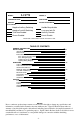
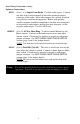
INSTALLATION INFORMATION MODEL : LCS770 SERIAL #: PURCHASE DATE: INSTALLER: DEALER: INSTALLATION DATE: OPTION JUMPERS Negative Auxiliary Switching Negative Park Kill Switching Two-Tone Enabled Phaser Disabled Audible Beep disable 8 sec.
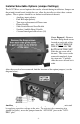
GENERAL DESCRIPTION The LCS770 Siren Amplifier is a premium 200W unit designed for single or dual 100W speaker use and full lighting control. The primary operating modes are Phaser, Yelp, Wail, Hands Free, Manual, Alert, and Radio. A Noise Canceling PA Override and push-button Horn Override are available in all modes. A manual push-button is provided for push-on/push-off tone toggle operation in the Phaser, Yelp, and Wail modes. It also allows manual siren control in the Manual or PA modes.
Installer Selectable Options (Jumper Settings) The LCS770 has several options that can be selected during installation. Jumpers on the printed circuit board, inside the case, allow the installer to select these various options. These options should be set before installation of the unit.
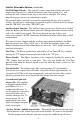
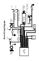
Installer Selectable Options (continued) Park Kill Input Polarity - The park kill (cutout) input turns off any siren tone output when activated (i.e. vehicle shifted into park, door opened, etc.), and remains off until a control on the siren is activated or changed. The wiring diagram on page 8 shows two connection examples. The park kill input is normally activated by connecting the gray wire to positive voltage.
MOUNTING SAFETY PRECAUTIONS For the safety of the installer, vehicle operator, passengers and the community please observe the following safety precautions. Failure to follow all safety precautions and instructions may result in property damage, injury and/or death. !!! WARNING !!! DO NOT mount in air bag deployment area. Devices should be mounted only in locations listed in SAE standard J1849. Controls should be placed within convenient reach of the driver. Assure clearances before drilling in vehicle.
Please follow these guidelines when wiring the siren: • Use only high quality crimp connectors. • Make sure all connections are tight. • Route wiring to prevent wear, overheating and interference with air bag deployment. • Use grommets and sealant when passing through compartment walls. • Minimize the number of splices to reduce voltage drop. • Ground connections should only be made to substantial chassis components, preferably directly to the negative of the vehicle battery.
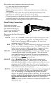
Siren Wiring Connections (CONTD) : Optional Connections: BLUE: (Pins 3 & 6) Input From Radio - Used for radio repeat. Connect one blue lead to each terminal of the radio speaker or output connector of the radio. Most radio outputs are isolated, in which case polarity would not be important. Radios with polarity sensitive outputs should be connected w/ the blue wire from pin 6 to the positive radio output, and the blue wire from pin 3 to the negative radio output. Use #18 AWG wire.
-8- SIREN AMPLIFIER VEHICLE HORN 12 - Brown (#14 AWG) 11 - Yellow (#18 AWG) 10 - Green (#18 AWG) 9 - Orange (#18 AWG) 8 - Gray (#18 AWG) 7 - Brown (#14 AWG) 6 - Blue (#18 AWG) 5 - Black (#14 AWG) 4 - Red (#14 AWG) 3 - Blue (#18 AWG) 2 - Black (#14 AWG) 1 - Red (#14 AWG) OR BATTERY + Positive Switching AUX Horn Jumper Selected Horn Switch/Relay +12 VDC + + SPEAKER 1 11 OHMS RADIO Door Switch Dome Light OR + +12 VDC +12 VDC Added Door Switch Negative Switching PK Jumper Selected SPEAKER
Light Wiring Connections: Red: (8 AWG) +12VDC Power - The two large red wires exiting the back of the siren should be connected to +12VDC through a fuse rated for the TOTAL current draw of ALL of the lights controlled by this unit. They will supply the power to the lights hooked up to the 9pin connector. You must connect BOTH red wires.
AMPLIFIER -10- BATTERY + Lights to be activated by Pushbutton Switch S4 Lights to be activated by Pushbutton Switch S2 Lights to be activated by Pushbutton Switch S3 Red (#8 AWG) Red (#8 AWG) FUSE Lights to be activated by Pushbutton Switch S1 Lights to be activated when Slide Switch is in Positions 1, 2, & 3 PIN 9 - WHITE (#12-16 AWG) - L3 PIN 8 - GRAY (#12-16 AWG) - L2 PIN 7 - VIOLET (#12-16 AWG) - S1 PIN 6 - BLUE (#12-16 AWG) - S3 PIN 5 - GREEN (#12-16 AWG) - S2 PIN 4 - YELLOW (#12-16 AWG) - S4
OPERATION GENERAL This unit is designed for easy operation under the stress associated with high-speed pursuit. Most siren functions are accessible with one simple motion without repetitive activation of switches or automatic timed switching that can interfere with desired operation. ON/OFF The On/Off-PA volume control (PA) will both turn the LCS770 unit on and off, as well as control the public address volume. It is located in the upper right hand corner of the front face.
LIGHT PUSH BUTTON SWITCHES Four push button switches are provided to enable four separate functions. The far left push button (possibly L. Alley) will control the item(s) connected to S1. The second push button (possibly R. Alley) will control the item(s) connected to S2. The third push button (possibly Takedown) will control the item(s) connected to S3. The fourth push button will control the item(s) connected to S4 (possibly gun lock). Each of these four outputs is protected with a 20A fuse.
MANUAL and HORN BUTTONS The front panel of the LCS770 contains two pushbuttons that operate the Manual function and the Air Horn. Manual – When the selector switch is in the Wail, Yelp or Phaser positions, pressing the MAN button cycles through to a generally quicker changing tone. (See table on page 12). These quicker tones are used at intersections and very highly congested areas. Pressing the button once changes to the next faster tone and pressing again changes the tone back to original tone.
VOLUME CONTROLS The radio repeat volume (Radio) control is recessed in the upper left hand corner of the front face. This should be set when the vehicle is parked. First set the volume level of the vehicle's two-way radio to its normal operating volume. Adjust the siren's rotary selector switch into the RADIO position. Insert a small, flat blade screwdriver into the RADIO volume adjustment port. Turn clockwise direction to increase the sound level.
SERVICE FUSES There are several fuses in this unit that protect it from shorts, spikes, and other such electrical problems that may possibly damage the unit. The HRT is protected internally by a 2 amp selfresetting fuse. This is not user serviceable, but will automatically reset once the short is removed. The entire unit is protected by a 20 amp automotive type fuse, located on the back of the unit. If your unit completely stops working, this fuse should be checked.
TROUBLESHOOTING This unit is designed to provide years of reliable service under even the worst conditions. Many times there may appear to be a problem with the unit when the true problem is in the speaker(s) or improper installation. The following chart shows typical symptoms and possible causes. Symptom No power Possible Cause Check On/Off PA Vol. Not ON Yellow wire is not powered Connector loose Siren 20A fuse blown Be sure the On/Off PA Vol.
PARTS The following parts are available from Signal Vehicle Products: Part S30235-13 S30234-13 SWH-49 SWH-48 P30069-38 P30056-16 P30028-1 P30232-1 P30208-10 P30032-8 P30239-1 P30253-3 P8070-254-1 S30007-66-3 P30007-66-1 P30230-19 P30147-44 P30050-28 P30147-117 Description Siren Top Cover Siren Bottom Mounting Plate 9-Conductor Wiring Harness for Lighting Functions 12-Conductor Wiring Harness for Siren Connections Microphone Bracket with Screws 1/4-20 x 3/8" Hex Locking Bolt 20 Amp Automotive Fuse Noise Can
LIMITED WARRANTY Signal Vehicle Products warrants this new product to be free from defects in material and workmanship, under normal use and service, for a period of one (1) year from the date of delivery to the first user-purchaser.