
Specifications


-8-
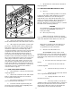
Figure 3-8. External Auxiliary Relay.
Refer to the instructions provided
with the switching device. Connect the +12VDC
ACTIVATED (1-ampere or less) switching device to
the violet wire.
b. If the PA and RADIO transmitter
are to have separate microphones, fold back and
insulate the violet wire.
7. External Auxiliary Relay.
When switch 11 of the control head is
not used for the common microphone function, it can
be used to activate an external relay. In addition to
the SmartSiren’s eight relay-controlled outputs, this
external relay can be used to activate another auxil-
iary device. Switch 11 can function only in a push-on/
push-off mode.
When switch 11 is activated, +12VDC
is supplied on the power cable’s violet wire. This
+12VDC is capable of supplying 1-amp., which should
be adequate for most automotive relays.
A 40-amp. relay (Federal Signal Part
No. 131A175) is recommended. Figure 3-8 shows the
wiring for any single pole relay. The pin numbers
shown are for the recommended Federal Signal relay.
8. Connection to Power Source (see
figure 3-6).
The SS2000SM must operate from a
12 volt NEGATIVE ground vehicle electrical system.
Therefore, before making any electrical connections,
verify the polarity of the vehicle electrical system
ground.
NOTE
Transient noise pulses caused by the automo-
tive power system or surge currents due to
switching inductive or incandescent lamp loads
may cause malfunctions in the SS2000SM
if proper wire routing is not followed.
The Amplifier Unit red (positive) power
cable lead should be as short and direct to the
fuse block or user-supplied switch (current
capacity of at least 20 amps) as possible. DO
NOT splice to accessory power leads.
The Amplifier Unit black (negative)
power cable lead should be as short and direct
to the fusible link on the front fender as pos-
sible. DO NOT splice to accessory negative
(black) leads.
IMPORTANT
The SS2000SM does not have an on-off
switch. If power is obtained directly from the
vehicle battery, the system will continuously
draw approximately 0.5A and will eventually
discharge the vehicle’s battery. It is RECOM-
MENDED that Amplifier Unit power
be obtained from a vehicle circuit that is
powered in the RUN, and START positions.
Power can also be obtained from a user-supplied
switch (current capacity of at least 20 amps).
CAUTION
Before drilling holes in ANY part of a vehicle,
ensure that both sides of the surface are clear
of parts that could be damaged; such as brake
lines, fuel lines, electrical wiring or other vital
parts.
a. Power for the Amplifier Unit can
be obtained from the vehicle’s fuse block; or a 20-
ampere fused, switched circuit. When obtaining
power from the vehicle’s fuse block, refer to the
vehicle’s wiring manual to ensure the unit will be
powered in the RUN and START positions.
Route the red (+) power cable lead
to the fuse block or user-supplied switch. When the
red (+) power cable lead is routed to the fuse block,
install the supplied fuse clip adapter as follows (see
figure 3-6):
(1). Slip the fuse clip adapter
over the fuse.
(2). Insert the adapter clip/fuse
into the applicable fuse block location (refer to the
vehicle’s wiring manual) with the adapter clip end
toward the top of the fuse block. Make sure that the
selected fuse block location is capable of supplying an
additional 20-amperes.
(3). Attach the power cable’s red
wire on the fuse clip.
290A4023-1
0
+12VDC
PRP. WIRE FROM SIREN
POWER CABLE, PIN 8
85 30
86
GROUND
87
AUXILIARY
DEVICE