
Specifications


-9-
b. To protect the wires, use the in-
line fuseholder and 20-ampere fuse. The fuseholder
and fuse should be installed in the red (+) lead as
close as practical to the power source.
c. Route the black (-) power cable
lead through the previously drilled hole into the
engine compartment, and through existing clamps
and holders toward the fusible link on the front
fender. DO NOT make any connections to the battery
until all other wiring is complete.
B. Light Bar and Auxiliary Light Connections.
The SS2000SM is programmed at the
factory to satisfy most installation requirements.
Before proceeding with installation, refer to the
supplied Operation and Configuration Instructions
for a description of the “standard” program, and
instructions on how to change the programming.
The SS2000SM provides two terminal
strips (TB1 & TB2) for control of light bars, auxiliary
lights and accessories. A total of eight fused relay-
controlled outputs are available.
Each output switches a nominal +12-volts
to the controlled device. Do NOT use the black wire
in the power cable for grounding the switched
device(s). Ground the switched devices separately.
Refer to the installation instructions
provided with the light bar or auxiliary light for
additional precautions and details.
IMPORTANT
Since the terminals labeled LIGHTS 1, 2, and 3
can be reprogrammed to activate in any of the
three modes, select the terminals used for the
various loads in accordance with the current
ratings of the terminals.
Primary rotating lights normally require more
current than flashing or secondary warning
lights. If, for example, primary rotating lights
are to be activated in Modes 2 and 3, connect
the rotators to LIGHTS 3 (rated at 40-amperes).
Then, reprogram the unit to activate the
LIGHTS 3 terminal in Modes 2 and 3.
Fuse current ratings and suggested uses for
each output are shown in table 3-1.
Complete the wiring to the light bar or
accessories as follows:
CAUTION
The relay board WILL be damaged if correct
polarity is not observed.
1. Remove the chassis cover by loosening
the 2 screws on the bottom of the unit. Slide the cover
to expose the relay board and terminal strips.
2. Route a #10AWG (minimum) red wire
through the hole labeled +BAT and attach it to the
large lug-type terminal (LUG1) on the relay board.
The lug is accessible through the top of the unit via
the hole labeled +BAT. Use a flathead screwdriver to
loosen and tighten this lug. Use a #8 AWG red wire if
the total light bar and auxiliary load currents exceed
50-amperes. Since this wire provides the power
source for all switched lighting functions, a good
mechanical and electrical connection here is impor-
tant.
3. Route this wire through the previously
drilled hole into the engine compartment and
through existing clamps and holders toward the
battery. Do NOT make any connections to the battery
until all wiring is complete.
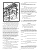
4. See figure 3-9. To protect the wire, 2
circuit breakers (CB1) rated at 50-amperes (Federal
Part No. 8474A176 or equivalent) should be con-
nected as close as practical to the positive (+) battery
terminal. When the total load current is greater than
50-amperes, use a 100-ampere circuit breaker. When
the total load current is less than 50-amperes, use a
50-ampere circuit breaker.
To use the Federal 50-ampere circuit
breakers (Part No. 8474A176) as a 100-ampere
Output Fuse / Rating Relay Suggested
Terminal Application
LIGHTS 1 F1 / 20-amps K1 Rear Flashing
LIGHTS 2 F2 / 20-amps K2 Front Flashing or
Secondary Warning
Lights
LIGHTS 3 F3A & F3B / K3 Rotating or Primary
two 20-amps= Warning Lights
40-amps total
A - E FA, FB, FC, KA, KB, Auxiliary Lights
FD, FE / KC, KD, (Takedown, Alley, etc.)
10-Amps. ea. KE
Note: Output E provides both normally open/normally closed
(NO/NC) and common contacts. By removing the fuse
labeled FE, it can be isolated from the +12-volt battery
supply for switching other POSITIVE voltages.
Table 3-1. Output Ratings.