
Specifications


-10-
circuit breaker, add the supplied jumper between the
two circuit breakers on the load side. DO NOT
remove the jumper on the battery side of the circuit
breakers.
WARNING
When making the following connections,
never exceed the current rating of the
circuit breakers (CB1) near the battery
(see figure 3-9). Failure to do this will
result in a shutdown of the vehicle
warning system.
5. See figures 3-5 and 3-10. Connect
wires from the light bar or accessories to TB1-1
through TB1-3 or TB2-A through TB2-E as appli-
cable. All wire connections for TB2 will be made with
the right angle plug. (See face plate for relay designa-
tors.) Refer to the instructions packed with the light
bar or accessory for proper wire gauge, current
requirements, and any additional instructions. Do
NOT exceed fuse ratings shown in table 3-1.
CAUTION
NEVER exceed fuse current ratings. Installa-
tion of higher current fuses WILL damage the
unit and void the warranty.
NOTE
Although output #3 is rated at 40-amperes,
the circuit is protected by two 20-ampere
fuses which are connected in parallel. TB1-3
(output #3) has two terminals in parallel to
obtain that rating.
6. When the current requirement for
LIGHTS 3 exceeds 30-amperes, split the load be-
tween the two terminals of TB1-3 or connect the two
terminals together with the supplied jumper (Federal
Part No. 233A198 or equivalent).
CAUTION
Personal injury, vehicle component damage,
and/or damage to the Amplifier Unit
will occur if the LIGHTS 3 terminal (TB1-3)
is shorted to the chassis. Before replacing the
chassis cover, ensure that the jumper (if in-
stalled) between the two terminals of TB1-3
will not short to the chassis.
7. Replace the chassis cover. Slide it
forward and secure with the two screws.
C. SignalMaster Connections.
WARNING
Do not connect more than one, 6 or 8
head, halogen SignalMaster assembly to
a SignalMaster controller or the
SignalMaster outputs of a SmartSiren.
Electrical fire or damage to the control-
ler or siren will result.
The Amplifier unit is not supplied with a
fuse installed for the SignalMaster. The kit contains
a 25-ampere and a 7.5-ampere fuse. Follow the
appropriate installation instructions depending on
the type of SignalMaster, halogen or LED.
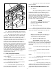
Figure 3-10. Relay Board.
290A4023-12
TIP OF
SCREWDRIVER
MATING
CONNECTOR
PRINTED
CIRCUIT
BOARD
CONNECTOR
STRIPPED WIRES
1. LOOSEN SCREW.
2. INSERT STRIPPED
WIRE IN CONNECTOR.
3. TIGHTEN SCREW.
10
10
10
10
20
20
20
20
10
321
CR2
CR1
CR6
CR8
CR7
CR12
CR11
CR10
CR9
CR5
CR4
R3
TB2
R5
R1
CR16
JP3
R2
CR14
F3B F3A F2 FAF1
FB FC FD FE
CR3
ABCDEFAUX
TB1
3
21
K2
K1
KA
KB
KD
KE
KC
K3
LUG1
MADE IN U.S.A.
FEDERAL SIGNAL CORP.
UNIVERSITY PARK, IL
2005100A
RELAY BOARD
RN1
JU1
R8
U1
U2
U3
C5
JP1
JP4
R7
C2
CR13
H1
CR15
C4
C1
C7
Q1
C6
C3
R6
R4
JP2
1
1
1
1
U4
RN2
2
C8
H2
JP5
R10
L1
H3
C10
R11
R9
C9
R12
A
A
CR17
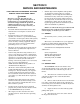
Figure 3-9. Battery Connections.
290A4023-11
FROM POSITIVE (
+
)
BATTERY TERMINAL
8 AWG, RED
50 AMP CIRCUIT
BREAKER (2)
CB1
FUSIBLE LINK,
TO NEGATIVE (
-
)
BATTERY TERMINAL
TO INTERFACE / RELAY
(
+
BAT) RED,
8/10 AWG
*
CHASSIS
GROUND
REQUIRED FOR AUXILIARY RELAYS
FROM INTERFACE / RELAY
(PI-4) BLK
*
BATTERY