
Specifications


-11-
c. Route user-supplied black 14-
gauge wire through the firewall and toward the
battery. Route the user-supplied red 14-gauge wire
toward the ignition terminal. Connect the red wire to
one end of the supplied 25-ampere circuit breaker
(Part No. 152118-25). Do not connect the other end of
the circuit breaker to the ignition terminal until ALL
wiring is complete.
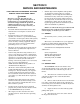
d. Strip 1/4" of insulation off each wire
at the eleven-position connector end. Insert the eight
22-gauge wires, the 16-gauge red wire, and the 14-
gauge red and black wires into the connector as
shown in figure 3-12. Tighten the screw at each
connector position to secure the wires in the connec-
tor.
e. As supplied in the kit, insert the
appropriate fuse (25-ampere for LED SignalMasters
or 7.5-ampere for Cuda TriOptic™, 6 or 8 module) in
the fuse holder in the back of the Amplifier unit.
D. Control Head Connections.
All connections between the SS2000SM
control head and Amplifier Unit are accomplished by
a single 20-foot telephone-type cable (provided). It is
terminated with modular-type connectors on each
end.
CAUTION
The unit will not operate if the telephone-type
cable is improperly wired. If it is necessary to
shorten the 4 conductor telephone-type cable,
ensure that the connections made to the
modular connector are exactly the same as the
original cable connections.
Figure 3-12. SignalMaster Eleven-position Connector.
1. Halogen.
a. Unless previously routed, route
the SignalMaster cable toward the Amplifier Unit.
Use caution to avoid scraping the wires on any sharp
edges.
b. Cut the cable to the appropriate
length as required.
c. Route user-supplied red and black
14-gauge wires through the firewall and toward the
battery. Connect the red wire to one end of the
supplied 25-ampere circuit breaker (Part No. 152118-
25). Do not connect the other end of the circuit
breaker to the (+) positive terminal until ALL wiring
is complete.
d. Strip 1/4" of insulation off each
wire at the eleven-position connector end. Insert the
eight 22-gauge wires, the 16-gauge red wire, and the
14-gauge red and black wires into the connector as
shown in figures 3-11 and 3-12. Tighten the screw at
each connector position to secure the wires in the
connector.
e. As supplied in the kit, insert a 25-
ampere fuse in the fuse holder in the back of the
Amplifier unit.
2. LED.
a. Unless previously routed, route
the SignalMaster cable toward the Amplifier Unit.
Use caution to avoid scraping the wires on any sharp
edges.
b. Cut the cable to the appropriate
length as required.
290A4023-1
4
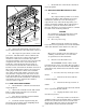
TIP OF SCREWDRIVER
MATING CONNECTOR
PRINTED CIRCUIT
BOARD
CONNECTOR
STRIPPED WIRES
1. LOOSEN SCREW.
2. INSERT STRIPPED
WIRE IN CONNECTOR.
3. TIGHTEN SCREW.
Figure 3-11. SignalMaster Connections.
A
U
X
3
2
E
1
A B C D
O
U
T
P
U
T N
O
N
C
C
LIG
H
T
S
+
B
A
T
SignalM
aster
FU
S
E
MIC
KEYPAD
S
ig
n
a
lM
a
s
te
r
S
m
a
rtS
ire
n
S
S
2
0
0
0
S
M
290A4023-13
B
(11) BLK 14AWG
-
GND
WHT (1)
1/4"
BRN (2)
GRN (3)
ORN (4)
PRP (5)
GRA (6)
YEL (7)
BLU (8)
RED (9)
9 CONDUCTOR CABLE FROM SIGNAL MASTER
(10) RED 14AWG
+
BAT
25 AMP BREAKER