
Specifications


To complete this portion of the installation,
proceed as follows:
1. Route the 20-foot cable between the
SS2000SM control head and the Amplifier Unit.
Secure the cable with user-supplied clamps and hold
downs as required.
2. Insert the modular connector in the
receptacle on the back of the SS2000SM Amplifier
Unit. Secure with user-supplied clamps and/or wire
ties to provide strain relief.
3. Insert the other modular connector in
the receptacle on the control head. Secure with user-
supplied clamps and/or wire ties to provide strain
relief.
E. Microphone Connections.
The SS2000SM is not supplied with a
microphone. A Federal Model MNCT-SB microphone
may be plugged into the microphone jack on the rear
of the Amplifier Unit.
If the Amplifier Unit is remotely mounted,
Model RMK (microphone extension kit) is available
from Federal. It includes a 20- foot extension cable
with phone plug, jack, and dashboard mounting
bracket.
Carefully route the extension cable through
the vehicle along with the telephone-type cable, and
secure with user-supplied clamps and ties as re-
quired.
3-7. INSPECTION AND FINAL INSTALLATION.
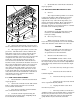
A. See figure 3-2. Secure the SS2000SM
Amplifier Unit to the mounting bracket with the
BLACK 1/4-20 x 1/2 hex head screws and 1/4 split
lockwashers. Ensure all fasteners are properly
tightened.
B. Before connection to the power source,
perform a visual check of all connections and wiring.
C. Ensure that there are no loose wire strands
or other bare wire which may cause a short circuit.
Also, all wires must be protected from any sharp
edges which could eventually cut through the insula-
tion.
D. Use an ohmmeter to verify that a short
circuit does NOT exist between the positive (+) and
negative (-) power cable leads. Also, there must be
NO short circuits between the positive (+) wires and
the vehicle chassis.
E. After performing steps 1 through 4, connect
all black (-) wires to the fusible link on the front
fender. Secure mechanical and electrical connections
are required.
WARNING
If wires are shorted to the vehicle frame
or each other, high current conductors
can cause hazardous sparks resulting in
electrical fires and molten metal.
Verify that no short circuits exist before
connecting to the Positive (+) battery
terminal.
DO NOT connect this system to the
vehicle battery until ALL other electri-
cal connections are made and mounting
of all components is complete.
Failure to observe this WARNING will
result in fire, burns and blindness.
F. Connect all #8 or #10AWG (minimum) red
(+) wires to the positive (+) terminal of the power
source. Also, connect a 14-gauge red wire from the
unused end of the 25-ampere circuit breaker (from
the SignalMaster connector) to the positive (+)
terminal of the power source. Again, secure mechani-
cal and electrical connections are required.
3-8. REPLACEABLE FUNCTION LABELS.
See figure 3-13. Replaceable function labels
identify the switches on the control head. A sheet of
applicable function legends is supplied.
To install the function legends, proceed as
follows:
-12-