
Specifications


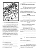

Figure 6-1. Control Head Disassembly.
-17-
E. Observe the slide switch connector’s orien-
tation and then disconnect the slide switch connector.
F. After repair or replacement, reconnect the
green wire and slide switch connector. Ensure the
slide switch connector is reconnected in the proper
orientation—white wire toward the edge of the
circuit board and the connector’s wires away from the
component side of the lower circuit board. Reas-
semble the control head using the previously re-
moved screws. Reassemble the control head in its
bracket (if used), and insert the modular connector in
the receptacle.slide switch connector is reconnected
in the proper orientation—white wire toward the
edge of the circuit board and the connector’s wires
away from the component side of the lower circuit
board. Reassemble the control head using the previ-
ously removed screws. Reassemble the control head
in its bracket (if used), and insert the modular
connector in the receptacle.
6-3. SLIDE SWITCH REPLACEMENT.
1. Disassemble the control head as described
in paragraph 6-2.
2. Observe the orientation of the slide switch.
Remove and retain the knob, the two torx head
screws and the switch bezel.
3. Place the new switch in position with the
same orientation as the old switch.
4. Secure the switch in position using the
previously removed switch bezel and phillips head
screws. Install the switch knob.
5. Reassemble the control head as described
in paragraph 6-2.
6-4. AMPLIFIER/SIGNALMASTER/RELAY UNIT.
A. General.
Any competent TV repairman or electronic
technician should have little difficulty in tracing a
malfunction, should any occur. For emergency
replacement of any of the small components, care
must be used when soldering. Heat easily damages
transistors, capacitors and circuit boards. It is
therefore advisable to use longnose pliers or a similar
heat sink on the lead being soldered.
CAUTION
To avoid damage to the unit, disconnect both
red wires to the SS2000SM at the battery
before proceeding.
B. Removal for Servicing.
When removing the chassis for servicing,
loosen the two hexagon head screws on the underside
of the unit. Slide the entire chassis out of the case.
CAUTION
Excess heat can damage the unit. When reas-
sembling, ensure that the cover’s vent slots
are positioned over the transformer.
C. Printed Circuit Board Removal.
The SS2000SM consists of three circuit
boards stacked on top of each other. The top board is
the relay board, the center board is the SignalMaster
Controller board, and the bottom board is the ampli-
fier board.
1. To remove the relay board, proceed as
follows:
a. Disconnect the wires from the
terminal strip TB1.
b. Disconnect the large red wire at
LUG1.
c. Disconnect the red, black, and red
wires at positions H1, H2, and H3.
d. Unplug the ribbon cable (JU1)
from the relay board.
e. The relay board is secured to the
amplifier board by four stand-offs. Remove and retain
the two relay board screws at the rear of the siren.
Depress the locking tab on the two stand-offs and
gently lift the relay board off the stand-offs.
SmartSirenSM
FEDERAL SIGNAL
O
F
F
1
2
3
290A4023-1
6
BEZEL
(TOP)
BASE
4-40 x 5/8" PHILLIPS
ROUND HEAD MACH.
SCREWS (4)
KEYBOARD ASSEMBLY