
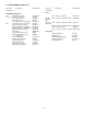
Specifications


-18-
2. To remove the SMC (SignalMaster
Controller) board, proceed as follows:
a. Remove the relay board as
described above.
b. Unplug all connectors and plug-in
type terminals from the printed circuit board.
c. Remove the four stand-offs which
secure the SMC board to the amplifier stand-offs.
3. To remove the amplifier board, proceed
as follows:
a. Remove the SMC board as de-
scribed above.
b. Unplug all connectors and plug-in
type terminals from the printed circuit board.
c. Remove the screws that secure
the output transistors.
d. Remove the four stand-offs which
hold the amplifier board to the chassis.
D. Control Head Fuse.
A solder-in sub-miniature fuse (F1 on the
amplifier board) provides short-circuit protection for
the control head and cable. F1 is located next to J3
(the phono jack) on the amplifier board. Failure of
this fuse, although unlikely, will cause the
SS2000SM to be completely inoperative. If failure of
F1 is suspected, proceed as follows:
1. Remove the amplifier board as de-
scribed in 6-3.C.2. above.
2. Check the fuse for continuity with an
ohmmeter.
3. If fuse failure has occurred, replace
with an EXACT replacement (refer to paragraph 6-
5.).
NOTE
Failure of the control head fuse is usually the
result of a shorted control head cable, or the
control head cable was damaged during instal-
lation. Ensure that the cause of F1’s failure is
located and repaired before reapplying power
to the unit.
E. Replacement of Output Transistors.
Failure of one or both of the output transistors
(Q3, Q4) is usually the result of a defective speaker
(short circuited voice coil). Rebroadcast of
unsquelched radio or music for long periods will also
have a detrimental effect on the output transistors,
and is therefore not recommended.
Federal recommends that both output transis-
tors be replaced should only one device prove to be
defective. This practice will ensure long periods of
service between failures.
When installing new output transistors, ensure
that the Sil-Pad insulators are installed between the
heat-sink and transistors.
F. Testing.
CAUTION
Make certain that the speaker is not defective
prior to installing the repaired SS2000SM.
WARNING
All effective sirens and horns produce
loud sounds (120 dB) that may cause
permanent hearing loss. Always mini-
mize your exposure to siren sound and
wear hearing protection. Do not sound
the siren indoors or in enclosed areas
where you and others will be exposed to
the sound.
After servicing is complete, perform a test
of all functions to ensure the siren is operating
properly.