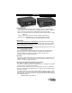
INSTALLATION AND INSTRUCTION MANUAL SS650SS650-013 SIREN LCS652LCS652-013 SIREN and Light Controller PLITSTR247 REV.
NOTICE Due to continuous product improvements, we must reserve the right to change any specifications and information, contained in this manual at any time without notice. Signal Vehicle Products and/or the manufacturer make no warranty of any kind with regard to this manual, including, but not limited to, the implied warranties of merchantability and fitness for a particular purpose.
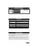
Installation Information SERIAL NO: DIP SWITCH OPTIONS PURCHASE DATE: _____ Negative Aux. Polarity DEALER: _____ Hands Free Enabled INSTALLATION DATE: INSTALLER: Model and serial number located on the bottom of the amplifier unit Specifications Input Voltage Audio Input Current Standby Current Output Power Siren Frequency High Voltage Protection Short Circuit Current Operating Temperature Size Boxed Weight 10 - 16 VDC (negative ground) 8 Amps @ 13.
Installation Notes Proper installation of the unit is essential for years of safe, reliable operation. Please read all instructions before installing the unit. Failure to follow these instructions can cause serious damage to the unit or vehicle and may void warranties. Qualifications The installer must have a firm knowledge of basic electricity, vehicle electrical systems and emergency equipment. Keep These Instructions Keep these instructions in the vehicle or other safe place for future reference.
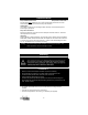
Electrical Connections Wire Size and Termination Electrical connections to this unit are made through the green 10-terminal connector located in the rear of the unit (P/N P30041-177). Examine the charts below to determine the proper gauge of the wire you should use. Please review the following recommendations to follow when making your installation: P30041-177 • Use only high quality crimp connectors. Make sure all connections are tight. • Minimize the number of splices to reduce voltage drop.
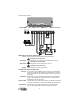
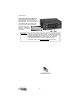
(Electrical Connections CONT’D) Program Button TONE SELECT Micro Feedback LED DIP SW. DIP Switches 10-Terminal Connector WARNING: ENSURE CONNECTOR IS FULLY INSERTED & SCREWS LOCKED 3 2 SPEAKER(s) 100/200W 5 Ignition 6 20 AMP FUSE Factory Horn Relay 4 Audio Power (+12VDC) 14 AWG 1 Ground (Batt. Neg.
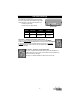
DIP Switch Settings The SS650 and LCS652 have two optional settings that can be selected during installation using the DIP switches located on the back of the amplifier case: • Auxiliary Input Polarity • Hands Free Cycler Mode Enable DIP Switches DIP SWITCH FUNCTION UP (Off) (default) 1 AUX Wire Polarity Positive switching Negative switching 2 Hands Free Cycler mode Hands Free Cycler mode disabled Hands Free Cycler mode enabled DOWN (On) DIP Switch 1 - Auxiliary Input Polarity (AUX Function) A
Optional Tone Programming The SS650 and LCS652 can be programmed to produce 6 different tones/sounds by activating its various functions: Function Wail Yelp Yelp Step Up Manual Horn Auxiliary Default Tone Wail Yelp Phaser Ramp Up Air Horn Air Horn Each of these functions can be programmed for a different tone if desired. If you would like to change the default sounds for any of the six functions, follow the instructions below. 1. Power the unit up. 2. Activate the function you wish to change.
Operation Wail/Off/Yelp Switch This is the 3-position button used for basic operation of the siren. While in the Wail or Yelp positions the siren will produce the tone programmed for that function (see previous page). The Wail and Yelp functions are defaulted for the Wail and Yelp tones. Wail Tone: A normal rise-fall tone used on highways and areas with low traffic or constant traffic flow. Yelp Tone: A rapid warble tone used in light to moderately congested areas.
(Operation CONT’D) Light Control Switches (LCS652 only) The LCS652 also has two additional switches located in the center of the face (SW1 and SW2). These two switches will control external devices (usually lights). SW1 controls the device connected to Terminal A on the rear connector. SW2 controls the device connected to Terminal B. Please Note: Terminals C and D of the connector (LCS652 only) supply the power for the devices switched by SW1 and SW2.
Troubleshooting Auto Shutdown This unit is designed to automatically shut down when certain undesirable conditions exist to prevent internal damage. All audio functions are disabled until the issue is corrected. • Over Voltage/Under Voltage • Over Current Micro Feedback LED This unit is designed with an LED that not only provides feedback when programming, but also helps troubleshoot audio issues.
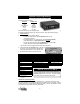
Parts Part S30235-19 S30234-19 SWH-152 30052-30 P30028-27 30032-8 30007-41 30007-42 SW-40 Description Amplifier Top Cover Amplifier Bottom Mounting Plate Optional Wiring Harness (not included) Rear Amplifier Case Screws 15 Amp Mini Automotive Blade Fuse for Amplifier TIP36C Power Transistor 3-Position Rocker Selector Switch (WAIL/YELP) Momentary Rocker Switch (HORN/MAN) Lighted ON/OFF Rocker Switch (LCS652) Service ONE YEAR LIMITED WARRANTY The manufacturer warrants each new product against factory defec