A Division of Star Headlight & Lantern Co., Inc. INSTALLATION AND OPERATING INSTRUCTION MANUAL SS650 SIREN AMPLIFIER LCS652 SIREN AMPLIFIER and LIGHT CONTROLLER 455 Rochester Street Avon, NY 14414 Telephone Number: (585) 226-9025 Toll Free Fax: 888-478-2797 www.star1889.com PLITSTR247 REV.
This page intentionally left blank
INSTALLATION INFORMATION MODEL: SS650-008___ or LCS652___ SERIAL NO: OPTIONS PURCHASE DATE: _____ Phaser Disabled DEALER: _____ Two-Tone Enabled INSTALLATION DATE: _____ Negative Aux.
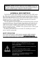
Important: Improper installation and/or use of these products may result in vehicular collision, personal injury and/or death. Star Headlight & Lantern Co., Inc., and its subsidiaries shall not be held responsible for damages directly or indirectly caused by improper installation or use of this product. GENERAL DESCRIPTION The SS650 and LCS652 Siren Amplifiers are designed for single 100W speaker use. Each comes standard with the amplifier unit and switch panel all in one unit.
GENERAL INSTALLATION Proper installation of the unit is essential for years of safe, reliable operation. Please read all instructions before installing the unit. Failure to follow these instructions can cause serious damage to the unit or vehicle and may void warranties. Qualifications The installer must have a firm knowledge of basic electricity, vehicle electrical systems and emergency equipment. Keep These Instructions Keep these instructions in the vehicle or other safe place for future reference.
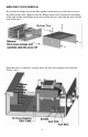
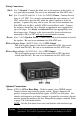
AMPLIFIER COVER REMOVAL If you need to change any of the three options listed above you will need to access the inside of the siren. Remove the two Philips head screws located on the bottom of the unit and the two Philips head screws from the rear, and slide the cover off the back of the unit. Bottom View Once the cover is removed, you may move the necessary jumpers over from the “Extra” slots.
MOUNTING AMPLIFIER The SS650 and LCS652 sirens may be mounted above the dash, below the dash, on a tunnel, or in a rack with the mounting u-bracket provided. Choose a mounting location convenient to the operator and away from any air bag deployment areas. Inspect behind mounting area for clearance. Assure adequate ventilation to prevent overheating. Consider wire routing and access to connections. Install mounting bracket to vehicle using 1/4" hardware (not supplied).
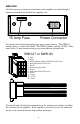
AMPLIFIER All of the necessary electrical connections to the amplifier are made through a connector located on the back of the amplifier case. -- 15 -10 7 11 8 12 9 15 Amp Fuse 4 5 6 1 2 3 Power Connector You should also find enclosed with your siren a wiring harness. The SWH-27 wiring harness is used in the SS650. The SWH-83 comes with the LCS652. They come with a 12-port connector using six or nine different colored leads.
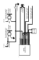
Wiring Connections: Black: (Pin 2) Ground - Connect the black wire to the negative of the battery, or to a good chassis ground. Be sure to use minimum size #16 AWG wire. Red: (Pin 1 for SS650 and Pins 1, 4 & 8 for LCS652) Power - Connect the red wires to +12 VDC. It is strongly recommended that you connect to a +12 VDC source that is present only when the vehicle ignition is in the on position. A power relay may also be used.
-8- SIREN AMPLIFIER 5 - No Connection USER 4 - Red (#14 AWG) (LCS652 Only) SUPPLIED FUSE 3 - White w/Brown Stripe (LCS652 Only) 2 - Black (#16 AWG) 1 - Red (#16 AWG) BATTERY + VEHICLE HORN Positive Switching AUX Horn Jumper Selected 9 - No Connection USER 8 - Red (#14 AWG) (LCS652 Only) SUPPLIED FUSE 7 - Brown (#16 AWG) 6 - White w/Orange Stripe (LCS652 Only) 11 - No Connection 10 - Green (#18 AWG) 12 - Brown (#16 AWG) Horn Switch/Relay +12 VDC OR +12 VDC Connect to the + side of the device op
OPERATION GENERAL This unit is designed for easy operation under the stress associated with high-speed pursuit. Most siren functions are accessible with one simple motion without repetitive activation of switches or automatic timed switching that can interfere with desired operation. MODE SWITCH The three-position rocker switch on the left controls the primary operating mode of the siren. WAIL - A normal rise-fall tone used on highways and areas with low traffic or constant traffic flow.
SIREN OUTPUT: Selector Switch Position: Speaker Output Pressing Manual Pushbutton Wail Yelp Wail Yelp Yelp Phaser (or Two-Tone) (Remains Yelp if Phaser disabled) OFF No Output Creates a manual WAIL tone while button is being held that sweeps down when the button is released. (NOTE: PHASER may be optionally disabled via program jumpers. See INSTALLER-SELECTABLE OPTIONS on pages 3 & 4). (NOTE: TWO-TONE may be optionally selected over Phaser via program jumpers.
TROUBLESHOOTING Symptom No power Possible Cause Power source not turned on Connector loose Amplifier 15A fuse blown Loose connection at power source No siren High voltage protection tone Bad speaker or speaker wiring Distorted Speaker assembly loose siren sound Intermittent Aux.
SPECIFICATIONS Input Voltage Input Current Standby Current Output Power Siren Frequency High Voltage Protection Short Circuit Current Operating Temperature Controls Connections (12-Pin Connector) Size Boxed Weight 10 - 16 VDC (negative ground) 8 Amps @ 13.6 VDC (100W speaker) Less than 20 mA 105 WATTS RMS MAX. (15.
LIMITED WARRANTY Signal Vehicle Products warrants this new product to be free from defects in material and workmanship, under normal use and service, for a period of one (1) year from the date of delivery to the first user-purchaser.
www.star1889.