MODEL 730 CE and RoHS Compliant OPERATING INSTRUCTIONS 1-800-257-3872 TOLL FREE 1-978-264-0292 FAX sales@setra.com EMAIL www.setra.
Setra offers a complete line of products for these industries: Industrial HVAC Test & Measurement Barometric Ultra High Purity/Sanitary Vacuum
Contents 1.0 Introduction ..............................................................................................1 2.0 Mechanical Installation .........................................................................1 3.0 Electrical Installation ...............................................................................5 4.0 Operation ....................................................................................................7 5.0 Calibration and Adjustment of Zero Output.................
1.0 Introduction Setra’s Model 730 capacitance manometer is a temperature compensated, absolute pressure transducer designed for accurate and repeatable vacuum measurements. Various full scale ranges are available from 10 Torr up to 1000 Torr. The units of measurement may be specified in Torr (mmHg), mBar, kPa, or PSIA. The Model 730 operates from a 12-30 VDC power supply and provides a 0-10 VDC signal output that is linear with pressure and independent of gas composition.
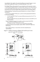
immediately, then replace the protective flange cover and store in an area where the temperature range is controlled between -20 to +85°C. The Model 730 can be mounted in any orientation on the vacuum system. To avoid the buildup of debris or condensable material in the measurement cavity of the Model 730 (which may cause measurement errors), we recommend that you install the Model 730 vertically with the tube facing down. Outline drawings showing the external dimensions are shown in Figure 1 (see below).
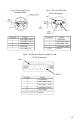
Figure 2: Outline Drawing of Model 730 with 5-pin Terminal Strip, and 0.5” and 0.25” OD Tube. Span Zero in. mm Pin 1 Mating Connector .69 17 Pin I 1.50 38 3.41 87 3.05 77 0.99 25 in mm Model 730 w/0.5” dia. Tube Mating Çonnector Pin 1 3.17 80 0.75 19 Model 730 w/0.25” dia.
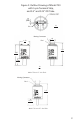
Figure 3: Outline Drawing of Model 730 with 6-inch cable and15-pin D-sub Terminal Strip, 0.5” and 0.25” OD Tube. Pin 1 3.24 82 Model 730 Model 730 Pin 15 0.99 25 3.0 76 0.50 13 Model 730 w/0.5” dia. Tube 0.75 19 0.25 13 Model 730 w/0.25” dia. Tube 4 in.
3.0 Electrical Installation The model 730 operates from a 12-30 VDC regulated power supply for the 0-10 VDC output version or from a 9-30 VDC regulated power supply for the 0-5 VDC output version. Either version can be specified with a 5 Pin terminal strip, 9 Pin D-sub, or 15 Pin D-sub on a 6 inch pigtail. Mating connectors are provided with the terminal strip version. The pinouts for each option are shown in figures 4, 5, and 6, Page 6.
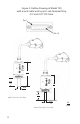
Fig. 4: Pin-out of 5-Pin Terminal Strip Fig. 5: Pin- out of D-sub 9-Pin Connector Pin 1 0.12 3.05 Span Zero Pin 1 in. mm Pin 9 1.50 38.10 Pin Location 1 2 3 4 5 Pin 1 Function +Signal Output Power Supply Common Power Supply + VDC Signal Output Common Not Used Pin Location 1 9 4 8 2,3,5,6,7 Function Power Supply Common Signal Output Common +Signal Output Case Ground Power Supply +VDC Fig.
4.0 OPERATION For most accurate pressure measurement, allow the Model 730 to warm up for at least 15 minutes. After installation, periodically check the zero output reading to verify correct output. Adjust the zero potentiometer if incorrect (See Section 5 for zero adjustment instructions). The signal output of the Model 730 is linear with pressure; e.g., for a 10 VDC FS Model 730, 10 VDC equals 100% FS output; 1 VDC equals 10% FS output.
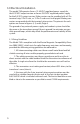
5.0 Calibration & Adjustment 5. 1 Checking & Zero Adjustment After installation on a system, the Model 730 should be zeroed. Figure 7 shows the location of the zero adjustment potentiometer. Note: Before making adjustments be sure to allow the Model 730 to warm up and pump down sufficiently to the system base pressure. This time will vary depending on range and system conductance. A minimum of 15 minutes is suggested. Use a digital voltmeter to view the signal output of the Model 730.
6.0 Maintenance & Troubleshooting There are no general maintenance requirements for the Model 730 other than periodic zero adjustment. If the unit fails to operate when received or if the unit appears damaged, notify Setra Systems or your supplier immediately. Retain packaging materials for inspection. Do not use if damaged. If the Model 730 is not going to be used immediately then replace the protective flange cover and store in suitable conditions described in Section 2.
7.0 Specifications Performance Data: Accuracy 1 Resolution: ± 0.5% of Reading Optional ± 0.25% of Reading Infinite. lmited only by output noise level (≤0.005% FS) Thermal effect:s Compensated Range: Zero Shift: Span Shift: Long Term Stability Proof Pressure: 0 to +50°C < ± 0.25% FS/50 °C < ± 1.35% Rdg/50°C ±0.
8.0 Returning the Model 730 for Repair Please contact a Setra application engineer (800-257-3872, 978-263-1400) before returning unit for repair to review information relative to your application. Many times only minor field adjustments may be necessary. If it is necessary to return the unit, please us the following: When returning the Model 730, please use the “Repair Order Return Form” (example below) found on our website at http://www.setra.com/tra/repairs/pdf/webrepair.pdf.
Calibration Services Setra maintains a complete calibration facility that is traceable to the National Institute of Standards & Technology (NIST). If you would like to recalibrate or recertify your Setra pressure transducers or transmitters, please call our Repair Department at 800-257-3872 (978-263-1400) for scheduling. 9.
SS730 Rev.A 07/29/2008 159 Swanson Road, Boxborough, MA 01719-1304 Tel: 800-257-3872/978-263-1400, Fax 978-264-0292 Email: sales@setra.com, Web: www.setra.