A Division of Star Headlight & Lantern Co., Inc.
INSTALLATION INFORMATION SERIAL NO: _________________________ PURCHASE DATE: ___________________ DEALER: ___________________________ INSTALLATION DATE: ________________ INSTALLER: ________________________ MODEL: SS741MG-007 OPTIONS _____ Alternate Magnum Tones _____ Two- Tone Enabled _____ Phaser/Man Auxiliary Override _____ Phaser Disabled Model and serial number located on the top of the amplifier unit TABLE OF CONTENTS GENERAL DESCRIPTION ...............................................................
Another feature allows cycling through Wail, Yelp, Phaser and Standby by providing a signal to the horn ring auxiliary wire when the function switch is in the Hands Free (HF) position. A Park Kill option is provided for connection to a door switch, etc. to disable the siren when exiting the vehicle. The PA volume control is provided on the front panel of the control head, while the Radio volume is on the amplifier box. The front panel is backlighted with LED’s for night visibility.
INSTALLER-SELECTABLE OPTIONS The SS741MG has several options that can be selected during installation. Jumpers on the back of the control head, as well as on the printed circuit board inside the amplifier case, allow the installer to select these various options. These options should be set before installation of the unit.
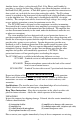
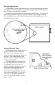
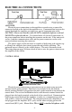
Park Ki ll Input Polarity The Park Kill (Cutout) Input turns off any siren tone output when activated, and remains off until a control is activated or changed. The wiring diagram on page 10 shows two connection examples. Connecting to positive normally activates the park kill input. To activate by connecting to ground (negative), move the “PKILL” option jumper from the “Pos. Switching” pins to the “Neg. Switching” pins in the amplifier unit. (See Amplifier diagram below).
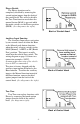
Phaser Disable The Phaser function can be completely disabled by removing the second option jumper from the back of the control head. This will also disable the Two-Tone function used when the manual button (MAN) is pressed while the mode switch is in the Phaser position (PHSR). (See diagram to the right).
Horn Ring Transfer The installer may opt to have the sirens electronic air horn replace the vehicle horn. This can be done by adding a single pole, double throw (SPDT) switch. Two Horn Ring Transfer wiring diagrams are shown below. MOUNTING SAFETY PRECAUTIONS For the safety of the installer, vehicle operator, passengers and the community please observe the following safety precautions. Failure to follow all safety precautions and instructions may result in property damage, injury or death.
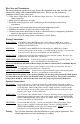
CONTROL HEAD The control head is designed to be flush mounted. Select a location such as the dash, the overhead console, or a center console. Choose a mounting location convenient to the Please note that for the SS741MG-TEC the 7 -position knob functions are reversed. operator and away from any air bag deployment areas. Be sure to choose a location that has at least two inches of depth to accommodate the control head and cables.
ELECTRICAL CONNECTIONS AMPLIFIER Electrical power connections to the amplifier are made using a removable connector located on the back of the amplifier case. Communication between the control head and the amplifier are made via a special communication cable. CAUTION: Please note that this cable IS NOT a standard telephone cord and CANNOT be replaced with one. You should make all electrical connections to the power connector before installing the connector on the unit.
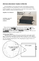
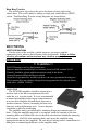
Wire Size and Termination The wiring diagram on the next page shows the minimum wire size used for each connection, along with recommended lead color. Please use the following guidelines when wiring your siren: • If the wire is longer than 10 ft. use the next larger wire size. Use only high quality crimp connectors. • Make sure all connections are tight. • Route the wiring to prevent wear, overheating and/or interference with air bag deployment.
SIREN Horn Switch/Relay -10- 2 - Black (#14 AWG) 1 - Red (#14 AWG) 4 - Red (#14 AWG) 3 - Blue (#18 AWG) 7 - Brown (#14 AWG) 6 - Blue (#18 AWG) 5 - Black (#14 AWG) 9 - Green (#18 AWG) 8 - White (#18 AWG) OR 11 - White w/Orange (#14 AWG) 10 - Orange (#14 AWG) 12 - White w/Brown (#14 AWG) Positive Switching AUX Horn Jumper Selected 1 and 4 - Red + VEHICLE HORN 2 and 5 - Black BATTERY Positive Switching AUX +12 VDC + RADIO OR + Door Switch Negative Switching PK Jumper Selected Positive Sw
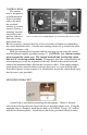
OPERATION Please note that for the SS741MG-TEC the 7 -position knob functions are reversed. GENERAL This unit is designed for easy operation under the stress associated with high-speed pursuit. Most siren functions are accessible with one simple motion without repetitive activation of switches or automatic timed switching that can interfere with desired operation. POWER In order for the siren to function, the power switch must be in the ON position.
HORN (Air Horn) This momentary push-button switch provides a simulated air-horn tone while pressed. This can be used to either replace, or to supplement the normal vehicle horn and is useful at intersections or in low noise areas. This tone will override all other siren tones. MAN (Manual Function) With the selector switch in the MAN, A LERT, or HF position, this momentary push-button switch (MAN) provides a manually activated Wail siren tone.
Magnum Mode: Rotary Switch Position: Phaser Yelp Wail Hands Free Speakers 1/2 Pressing Manual Pushbutton 1/2 Wail/Phaser Double Yelp (Staggered) Double Wail (Staggered) No Output Wail/Two-Tone Yelp/Phaser Manual No Output Alert No Output Wail/Yelp Creates two staggered manual WAIL tones while button is being held that sweep down when the button is released. Creates two staggered manual WAIL tones while button is being held that sweep down when the button is released.
VOLUME CONTROLS Radio Repeat Volume - The radio repeat volume is recessed on the front face of the amplifier next to the communication jack. This should be set when the vehicle is parked. First set the volume level o f the vehicle’s two-way radio to its normal operating volume. Adjust the siren’s rotary selector switch into the RADIO position. Insert a small, flat blade screwdriver into the RADIO volume adjustment port. Turn clockwise direction to increase the sound level.
TROUBLESHOOTING Symptom No power Possible Cause Check Power switch not turned on Connector loose Amplifier 15A fuse blown (one or both) Loose connection at power source No siren tone - PA works High voltage protection Low voltage protection Microphone button stuck Park Kill polarity option set wrong Park Kill activated No siren tone - No sound Bad speaker or speaker wiring No PA PA volume not set properly Distorted Speaker assembly loose siren sound Intermittent Aux.
If you are experiencing an unusually high amount of RFI, you may perform the following steps to help reduce the RFI: 1. Make sure that both the control head and amp are securely attached to good chassis ground (i.e. no paint in-between the chassis and the grounding terminal). 2. Keep the siren control head and the police radio as far away from one another as is practical. 3.
PARTS The following parts are available from Signal Vehicle Products: Part P30235-4 P30234-4 SWH-31 P30069-38 P30053-31 P30028-8 P30028-6 P30232-1 P30208-10 P30032-8 P30239-1 P30239-2 P30148-8 Description Siren Top Cover Siren Bottom Mounting Plate Wiring Harness Microphone Bracket with Screws Amplifier Case Screws 5 Amp Automotive Blade Fuse for Control Head 15 Amp Automotive Blade Fuse for Amplifier Noise Cancelling Microphone Microphone Strain Relief TIP36C Power Transistor Rotary Selector Switch Knob
SPECIFICATIONS Input Voltage 10 - 16 VDC (negative ground) Input Current Standby Current Audio Frequency Audio Output Output Power 16 Amps @ 13.6 VDC (dual 100W speakers) Less than 150 mA 200Hz - 10 kHz + 3db 40 watts @13.6 VDC (single 100W speaker) 105 WATTS RMS MAX. (15.0 VDC - single 100W speaker) 210 WATTS RMS MAX. (15.
-19- THIS INNER AREA TO BE CUT OUT. CAUTION: Do not cut inner area too large, control head face plate only overlaps 1/8". 1/2" 1/8" 2-5/8" CONTROL HEAD INSTALLATION TEMPLATE 5-1/4" 5-7/8" Ø.