
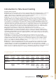
Specifications

G
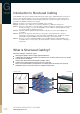
STRUCTURED
CABLING
TM
www.signamax-eu.com
G4
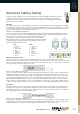
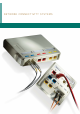
Testing has a major significance for the correct functionality of structured cabling. Testing devices are able
to measure installed components and determine whether all requirements defined in the international
standards necessary for reliable operation have been met. For Category 5e and Category 6 the following
main parameters are measured:
Wire Map
This parameter checks the correct termination of cable wires in telecommunication outlets and patch panels, including
the shielding in STP cabling. At the same time, it checks the signal throughput on the whole cable length—i.e. it is able
to show any open-circuit or short circuit faults. The Wire Map parameter is very important but in itself it cannot ensure
the correct functionality of an installed computer network.
What to do if the Wire Map parameter fails?
First, it is necessary to check whether the individual wires have been installed correctly in the termination block. If so
(i.e. the wire map corresponds to the standardized T568A or T568B schemes) and the Wire Map parameter still fails,
there could be several causes for this: an incorrectly terminated wire in the
termination block, a wire interruption inside the cable, or a short-circuit.
Advanced testing devices are able to determine the location of the fault with
a relatively high accuracy and by doing so make fixing the problem easier.
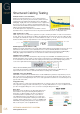
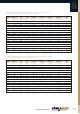
T568A and T568B wire map schemes:
NEXT (Near End Cross Talk)
NEXT is the value that expresses how much signal can get from one pair to another pair within one cable.
The measurement of cross-talk at the near end takes place at the same end of the cable as the location of the signal
source. For this parameter, all combinations of pairs are measured within one cable—i.e. 12-36, 12-45, 12-78, 36-45,
36-78, 45-78. This measuring is done for both ends.
What to do if the NEXT parameter fails?
First, it is essential to find out at which end of the cable NEXT is showing the error (this function is supported by all
advanced testing devices). Then it is necessary to check the maximum permitted unlaid of wires in one pair on the
termination block—that should not be more than 13 mm. Typically for category 6, the 13 mm does not necessarily
ensure that the NEXT parameter will pass so it is essential to keep the pair unlaid as short as possible. It is also
important that the original twisting of each pair is preserved during installation and that there is no air core between
the twisted wires in a pair. A frequent source of cross-talk problems can also be the use of cable couplings. Hence if
a cable is not long enough, it is better to replace it with a cable of a corresponding length rather than use couplings.
Attenuation
Attenuation shows the difference between the strength of the initial signal and the strength of the signal after it gets
to the other end of the wire. It is caused mainly by the wire resistance and is usually larger for higher frequencies.
Attenuation also increases as the diameter of the cable decreases—this means that a cable with a size of AWG 24
has a slightly higher attenuation than an AWG 23 cable.
What to do if the attenuation parameter fails?
The length of the horizontal cable must be checked—i.e. whether the electrical length of the link (the actual length of
the twisted pairs inside the cable) corresponds to the maximum permitted permanent link of 90 m. A frequent cause
of higher attenuation is also an incorrectly terminated wire in patch panels, outlets, or keystones.
T568A
1. white-green
2. green
3. white-orange
4. blue
5. white-blue
6. orange
7. white-brown
8. brown
T568B
1. white-orange
2. orange
3. white-green
4. blue
5. white-blue
6. green
7. white-brown
8. brown
Structured Cabling Testing