OPERATION, PARTS AND SAFETY MANUAL MANUAL DE OPERACIÓN, PARTES Y SEGURIDAD BXT2 BATTERY-HAND TOOL FOR PLASTIC STRAPPING APARATO PORTÁTIL CON ACUMULADOR PARA FLEJADO CON CINTA PLÁSTICA IMPORTANT! DO NOT DESTROY It is the customer’s responsibility to have all operators and servicemen read and understand this manual. Contact your local Signode representative for additional copies of this manual.
SHORT INSTRUCTIONS The most important points in brief! Charging battery / Cargar acumulador / Akku laden 1. Insert battery / Inserte acumulador / Akku einsetzen 3. 2. red / rojo / rot Error / Defecto / Fehler green / verde / grün 1st charge > 5 hr / Recharging approx. 20–40 min. 1. cargar > 5 hr / Recargar aprox. 20–40 min. 1. Laden > 5 Std. / Aufladen ca. 20–40 min.
INSTRUCCIÓNES BÁSICAS KURZANLEITUNG ¡La mayoría de los aspectos! Das Wichtigste in Kürze! Operating panel / Panel del operación / Bedienpanel Battery charge / Carga de la batería / Akku-Ladezustand ✓ green / verde / grün ➟ ➟ ➟ ✓ Recharge Recargar Aufladen red / rojo / rot Mode of operation / Modo operativo / Betriebsart AUTO MAN. SOFT ➟ +/- +/- AUTO MAN. SOFT AUTO MAN. SOFT Semi-Auto / Semiautomático / Halbautomatisch: ➟ AUTO MAN. SOFT AUTO + MAN.
SIGNODE BXT2 SIGNODE ENGINEERED PRODUCTS Hand Tool Division 3610 W. Lake Avenue, Glenview, Illonois 60025 TABLE OF CONTENTS SHORT INSTRUCTIONS 1 Technical data 2 General information 2.1 Information on environmental protection 3 Safety instructions 4 Description 4.1 Construction 4.2 Operating panel 4.3 Function 5 Operating instructions 5.1 Charging the battery 5.2 Operating the tool 5.3 Checking the seal 5.4 Checking battery charge 5.5 Setting mode of operation 5.6 Setting strap tension 5.
SIGNODE BXT2 CONTENIDO Página INSTRUCCIÓNES BÁSICAS 2 1 Información técnica 5 2 Generalidades 9 2.1 Indicaciones ecológicas 9 3 Disposiciones de seguridad 11 4 Descripción 13 4.1 Construcción 13 4.2 Panel de operación 13 4.3 Principio de operación 13 5 Operación 15 5.1 Cargado del acumulador 15 5.2 Operación del aparato 15 5.3 Inspección de soldadura 19 5.4 Comprobar carga del acumulador 19 5.5 Ajustar modos de operación 19 5.6 Ajuste de grado de tensado 21 5.7 Ajustar tensión suave 21 5.
SIGNODE BXT2 1 TECHNICAL DATA Weight 3.9 kg (8.6 lbs.) (incl. battery) Dimensions Length Width Height Strap tension (0) 900–2500 N (200–560 lbs.) Soft: 400–1500 N (88–335 lbs.) Tension speed 220 mm/s (8.6“/s) Sealing Friction weld Emission sound pressure levels, measurement type A (EN ISO 11202) LpA 82 dB (A) Vibrations at handle (EN ISO 8662-1) ah,w 2.2 ms-2 370 mm (14.5“) 138 mm (5.4“) 148 mm (5.
SIGNODE BXT2 1 INFORMACIÓN TÉCNICA 1 TECHNISCHE DATEN Peso 3,9 kg(incluye acumul.) Gewicht 3,9 kg Dimensiones Largo 370 mm Ancho 138 mm Alto 148 mm Abmessungen Länge 370 mm Breite 138 mm Höhe 148 mm Tensión (0) 900–2500 N Suave: 400–1500 N Spannkraft (0) 900–2500 N Soft: 400–1500 N (inkl.
SIGNODE BXT2 2 WARNING ATENCIÓN GENERAL INFROMATION These operating instructions are intended to simplify familiarisation with the strapping tool and its proper use for the intended purpose. The operating instructions contain important information concerning the safe, proper and efficient use of the strapping tool. The operating instructions must always be available at the place of operation of the strapping tool. They must be read and observed by all persons working with or on the strapping tool.
SIGNODE BXT2 2 GENERALIDADES 2 ALLGEMEINES Este instructivo de operación está destinado a facilitar el conocimiento del aparato y su correcta utilización conforme a las disposiciones. El instructivo de operación contiene importantes indicaciones para el empleo seguro, apropiado y económico del aparato. Diese Betriebsanleitung soll das Kennenlernen des Gerätes und den bestimmungsgemässen Einsatz erleichtern.
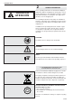
SIGNODE BXT2 WARNING ATENCIÓN 3 SAFETY INSTRUCTIONS Inform yourself! Read the operating instructions carefully. Preventive and corrective maintenance on the tool may only be carried out by trained personnel. Protect yourself! When operating the tool, wear eye, face and hand protection (cut-proof gloves). Power source! Before starting preventive or corrective maintenance, remove battery from the tool. Always inspect the electrical plug and cable before use.
SIGNODE BXT2 3 DISPOSICIONES DE SEGURIDAD 3 SICHERHEITSVORSCHRIFTEN ¡Infórmese! Lea cuidadosamente este instructivo antes de utilizar el aparato. El aparato sólo deberá recibir mantenimiento y ser reparado por personal cualificado. Informieren Sie sich! Vor dem Gebrauch des Gerätes die Betriebsanleitung sorgfältig lesen. Das Gerät darf nur von ausgebildetem Personal gewartet und instandgesetzt werden. ¡Protéjase! Al trabajar use protecciones de seguridad ocular, facial y manual (guantes irrompibles).
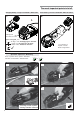
SIGNODE BXT2 4 4.1 CONSTRUCTION 1 3 AUTO MAN. SOFT 2 +/- +/- DESCRIPTION AUTO MAN. SOFT 4 1 2 3 4 5 6 7 8 9 5 9 Operating panel Tension button „Strap tensioning/welding“ (Fully-Auto) Handle Battery, 14.4 V Rocker lever Welding button „Welding/cutting“ (manual) Welding/Cutting Tensioning Battery charger For detailed information, refer to the operating instructions for the battery and battery charger. 6 7 8 Fig. 1 1 2 4.2 OPERATING PANEL 3 1 2 3 4 5 6 7 9 AUTO MAN.
SIGNODE BXT2 4 4 DESCRIPCIÓN 4.1 CONSTRUCCIÓN 1 Panel de operación 2 Tecla de tensado “tensado de fleje/soldadura“ (todo automatico) 3 Asa portadora 4 Acumulador, 14,4 V 5 Palanca basculante 6 Tecla de soldadura “soldar/cortar“ (manual) 7 Corte y soldadura 8 Tensora 9 Cargador del acumulador Para informes detallados vea el manual de operación adjunto para el acumulador y el cargador. 4.1 AUFBAU 1 2 3 4 5 6 7 8 9 4.
SIGNODE BXT2 5 1 ORERATING INSTRUCTIONS 5.1 CHARGING THE BATTERY 2 – Connect battery charger AL 1860 CV (4/2) to mains supply. – Insert battery 14.4 V (4/1) into battery charger slot. The charging process and error functions are indicated by a green (4/3) and a red light (4/4). For detailed information, refer to the operating instructions for the battery and battery charger. Charging times: – First charging of a new battery, min. 5 hr. – Recharging of empty battery: approx.
SIGNODE BXT2 5 OPERACIÓN 5 BEDIENUNG 5.1 CARGADO DEL ACUMULADOR – Conectar el cargador AL 1860 CV (4/2) a la red eléctrica. – Colocar acumulador (14,4 V) (4/1) en el enchufe de carga. El proceso de cargado y las anomalías se señalan mediante un indicador verde (4/3) y uno rojo (4/4). Para mayores detalles vea el manual de operación adjunto para el acumulador y el cargador. Tiempos de cargado: – La primera vez para un acumulador nuevo, mínimo 5 horas. – Recargado de acumulador vacío: aprox 20 a 45 min.
SIGNODE BXT2 1 – Take the tool in the right hand and lift the rocker lever (6/1) towards the handle. – Slide the straps, one on top of the other, into the tool up to the stop. The strap lead is now approximately 5 cm (2“) beyond the tool. – Release the rocker lever. Fig. 6 – Press the tension button (7/1) until the preselected strap tension is reached. The tool switches over automatically as soon as the strap tension has been reached. The straps are welded and the upper strap cut off.
SIGNODE BXT2 – Tome el aparato con la mano derecha y tire la palanca basculante (6/1) contra el asa portadora. – Las cintas sobrepuestas deberán ser insertadas hasta el tope en el aparato. El inicio de la cinta deberá sobresalir unos 5 cm por delante del aparato. – Gerät mit der rechten Hand fassen und Wippenhebel (6/1) gegen den Traggriff ziehen. – Die übereinanderliegenden Bänder bis zum Anschlag in das Gerät einlegen. Der Bandanfang ragt ca. 5 cm über das Gerät hinaus. – Suelte la palanca basculante.
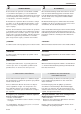
SIGNODE BXT2 5.3 CHECKING THE SEAL 1 – Check appearance of seal (see fig. 9) regularly. If the straps are poorly welded, check the welding time setting (refer to chapter 5.8). 1 Good seal (the complete surface is cleanly welded without excess material being forced out sideways). 2 Poorly welded seal (not welded over the complete surface), welding time too short. 3 Poorly welded seal (excess material is forced out sideways), welding time too long. 3 2 Fig. 9 5.4 CHECKING BATTERY CHARGE 1 2 3 Fig.
SIGNODE BXT2 5.3 INSPECCIÓN DE SOLDADURA 5.3 VERSCHLUSSKONTROLLE – Revise siempre el aspecto de la soldadura (ver fig. 9). Si la calidad del soldado no es satisfactoria: Revise el tiempo de soldadura (ver capítulo 5.8). 1 Buena soldadura (El área de la unión se encuentra perfectamente soldada, y sin material fundido excedente saliendo a los lados). 2 Soldadura defectuosa (soldadura no cubre toda la superficie de la unión), el tiempo de soldadura está ajustado insuficientemente.
SIGNODE BXT2 1 2 ➟ 5.6 SETTING STRAP TENSION 3 – Press the „Function“ button (12/1) briefly. – Press the „Strap tension“ button (12/2) until the flashing digital display (12/3) shows the required strap tension. Wait two seconds until the new setting is saved. 1 = min. strap tension approx. 400/900 N* (88/200 lbs.) (PP) 9 = max. strap tension approx. 1500/2500 N* (335/560 lbs) (PET) * refer to Chapter 5.7 = +/- Fig. 12 1 5.7 SETTING SOFT TENSION 2 ➟ AUTO MAN. = SOFT AUTO MAN. AUTO MAN.
SIGNODE BXT2 5.6 AJUSTE DE GRADO DE TENSADO – Oprima brevemente la tecla “Función” (12/1). – Oprima la tecla “Tensión de fleje” (12/2) hasta que el indicador digital parpadeante (12/3) muestre la tensión requerida. (espere unos dos segundos para que este valor quede almacenado). 1 = Tensión mínima aprox. 400/900 N* (PP) 9 = Tensión máxima aprox. 1500/2500 N* (PET) * ver capitulo 5.7 5.7 AJUSTAR TENSIÓN SUAVE 5.6 SPANNKRAFT EINSTELLEN – Drucktaste „Funktion“ (12/1) einmal kurz betätigen.
SIGNODE BXT2 – Remove three cylinder screws (16/2). – Lift the rocker lever towards the handle, remove cylinder screw (16/4) together with the strap stop rear 13 mm (16/3). – Remove cover (16/1). – Remove oval head screw (16/7) and remove strap guide rear 13 mm (16/6) from lever. – Install cover (16/1). – Mount strap stop rear 16 mm (16/5). 7 6 5 b) Change strap width from 15–16 mm to 12–13 mm – Mount 13 mm strap stop (15/1) and secure sunk screw (15/2) with Loctite 222.
SIGNODE BXT2 – Afloje los tres tornillos cilíndricos (16/2). – Lleve la palanca basculante hacia el asa, extraiga el tornillo cilíndrico (16/4) junto con el tope de cinta trasero de 13 mm (16/3). – Extraiga la cubierta (16/1). – Extraiga el tornillo lenticular (16/7) y quite la guía de fleje posterior de 13 mm (16/6) de la palanca. – Reinstale la cubierta (16/1). – Coloque el tope de cinta trasero de 16 mm (16/5). – Drei Zylinderschrauben (16/2) lösen.
SIGNODE BXT2 7 PREVENTIVE/CORRECTIVE MAINTENANCE 7.1 CLEANING/REPLACING TENSION WHEEL 5 1 2 3 4 Removal – Remove battery from tool. – Remove four cylinder screws (19/4) and remove strap stop rear (19/5) and cover (19/3). – Remove tension wheel (19/1) carefully. Remove ball bearing (19/2) from tension wheel. – Clean the tension wheel with compressed air (wear goggles). – If the tension wheel teeth are covered with heavy dirt, they must be carefully cleaned with the wire brush supplied.
SIGNODE BXT2 7 MANTENIMIENTO Y SERVICIO 7 WARTUNG UND INSTANDSETZUNG 7.1 LIMPIEZA/REEMPLAZO DE RUEDA TENSORA 7.1 SPANNRAD REINIGEN/ERSETZEN Desmontaje – Extraiga el acumulador del aparato. – Extraiga los cuatro tornillos cilíndricos (19/4), y quite el tope de cinta trasero (19/5) y la cubierta (19/3). – Extraiga la rueda tensora (19/1) con precaución. Quite el rodamiento acanalado (19/2) de la rueda tensora. – Sopletee la rueda tensora (use gafas protectoras).
SIGNODE BXT2 7.4 TROUBLE SHOOTING If a malfunction occurs, the digital display blinks and displays error “E” followed by the error number. FAULT / AVERÍA / STÖRUNG E + E11 E20 E22 E23 E37 FAULT: Rocker lever was operated before the cooling-down period had elapsed. ACTION: – Operate the rocker lever only when the cooling-down period has elapsed.. FAULT: The battery used is not the right type. CAUSE: – Wrong battery. ACTION: – Use the correct battery. – Restart by removing/replacing the battery.
SIGNODE BXT2 7.4 ELIMINACIÓN DE AVERÍAS 7.4 BEHEBEN VON STÖRUNGEN Si ocurriera alguna anomalía, el indicador digital parpadeará desplegando “E” (Error) seguido del número correspondiente. Tritt ein Fehler auf, blinkt die Segment-Anzeige und zeigt einen Fehler „E“ an, gefolgt von der Fehlernummer. AVERÍA: La palanca basculante fue activada antes del periodo de enfriamiento. ELIMINACIÓN: – Actúe la palanca basculante luego del periodo de enfriamiento.
WEAR PARTS / RECOMMENDED SPARE PARTS DESCRIPTION Tension wheel Tooth plate Knife Battery, 14 V / 2,6 AH Li-Ion Battery, 14 V / 2,6 AH Li-Ion, US 46 53 166 222 222 28 Cylinder pin, Ø10x50 Roll pin, Ø6X26 / BN 881 Slide bearing, Ø10/12x10 Slide bearing, Ø8/10x8 Tooth plate bottom Set screw Bevel wheel with pinion, 15/32 Free-wheel needle bear.
53 54 55 56 57 59 60 61 62 64 65 66 67 68 70 71 72 73 74 75 76 77 78 79 81 82 83 84 85 86 87 88 89 90 91 92 95 96 97 Tooth plate Pan head screw Strap stop, front 13mm Pawl shaft Pawl wheel Retaining ring, Ø5 Bolt Blocking pawl Retaining ring, Ø8 Bolt Spacer disk, Ø5/10x0.
Bolt Screwed shaft Lower linkage Upper linkage Compression spring, Ø9.8x3x27.4 Swivel bearing Ball bearing, Ø7/19x6 Excentric shaft Spacer disk, Ø10/22x0.5 Needle bearing, Ø10/17x12 Welding shoe Ball, Ø5 Supporting disk Pinion Toothed belt, 158-2MGT-9 Washer Cylinder screw, M4x8 Bolt Knife Flanged bushing Compression spring, Ø4.2x0.8x11 Compression spring, Ø4.1x0.
Opcion: Guida del fleje 9mm Opcion: Conexión de alimentación Conectador de las cañerías 230V EU Conectador de las cañerías 115V US Option: Protection cover PT-Screw, KA 35x30 PT-Screw, KA 35x14 Option: suspension bow-set Cylinder screw, M4x20 Cylinder screw, M5x16 Option: Strap guide set 9mm Option: Power supply connection Mains Connector 230V EU Mains Connector 115V US 428873 428899 428900 428901 428874 428875 428876 428877 428878 31 Bold = Recommended spare parts Negrilla = Partes recommenda
12 116 Fig. A 50 5 14 60 13 61 41* Loctite 222 183 * 15 65 54* 136 59 66 53 1 73* 112 131 64 74 116 118 117 117 55 3 84 83 85 43* 4 72 71 103 75 110 111 109 5 82 81 18 76* 132 108 20 70 BXT2 OR-T 250 19 86* 5 66 131 135 6 127 25 32 9 130 90 89 41* 36 42 163 162 10* 164* 125 124 74 28 44 39 40 74 18 168 1832-002-023/1.1 35 45 46 18 172 169 178 41* 175 76* 177 167 168 26.06.09 wr/hp 07.
Fig. B (242) (248) 234 251 239 245 (247) (236) (241) Options 198 199 200 76 201 192 186 BXT2 Fig. A/1 202 197 259 WARNING 191 203 197 212 197 168 1832-002-023/1.1 206 204 Inspect all parts daily and replace them if they are worn or broken. Failure to do this can affect a product’s operation and could result in serious personal injury. 77 205 224 227 77 215 26.06.09 wr/hp 228 189 229 186 07.
SIGNODE BXT2 NOTIZEN 34 07.
SIGNODE BXT2 NOTES 07.
SIGNODE BXT2 SIGNODE NEW TOOL WARRANTY Signode Engineered Products Warrants that a new Signode strapping tool will operate per functional specifications for a period of sixty (60) days after the date of shipment to the owner’s place of business. Normal wearing parts, as outlined in the Operation, Parts & Safety manual, are covered by a thirty (30) day warranty unless, in Signode’s judgement, these parts have been subjected to abnormal or extreme usage.