BXT 2 BXT 2-19 Maintenance Manual ak 03.
BXT 2 BXT 2-19 Content: 1. Preface .................................................................................................................................................................. 3 2. Basic Innovations ................................................................................................................................................... 3 3. Tool Design.......................................................................................................................
BXT 2 BXT 2-19 1. Preface The objective of this maintenance manual is to familiarize a skilled technician with the tools particular features and enable him to repair and maintain it independently. Current issues of the operating instructions and the concerning product information sheets are essential elements of this manual and have to be checked as well. 2.
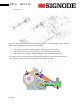
BXT 2 BXT 2-19 3. Tool Design 3.1. Housing/electrical components: The housing is carried out in 3 pieces. All processes are controlled and monitored by the Printed circuit board (pos. 198). The PCB interacts via the signal cable (pos. 202) with the motor power electronics (pos. 212). The power electronics is required to run the brushless motor. You can find a schematic wiring diagram in chapter 13. ak 03.
BXT 2 BXT 2-19 3.2. Welding unit The unit is lowering automatically when the welding process is started. Depending on the direction of motor rotation (freewheels) this is taking place as follows: 1. The cam ring (pos 109) is turning towards the switching cam (pos. 140, 143). 2. This forces the switching cam to go up and to push the welding unit downwards. 3. The eccentric axe (pos.155) is driving the welding shoe via needle bearing (pos.
BXT 2 BXT 2-19 3.3. Rocker lever and reset The Blocking Pawl (pos. 65) prevents the tension gear from turning backwards during tensioning. After strapping has taken place, the rocker lever (pos.89) is pulled, the pawl and therewith the tension is released. The reset cam (pos. 72) brings the welding unit back to its initial position. The Micro switch (Part of pos. 103) scans the position of the rocker lever. When the lever is pulled, the PCB does not allow initiating any function. 3.4.
BXT 2 BXT 2-19 3.5. Tensioning gear There is a free wheel integrated into the bevel gear pinion (Pos. 132). Provided the appropriate turning direction the free wheel delivers the torque to the 2 stage planetary gear and the tension wheel. To loose the tension the ring gear (Pos.19) is released by the pawl axle (Pos. 59). See also chapter 3.3). 3.6. Side cover with strap guides The strap guide (Pos. 179) is integrated into the side cover. To set up the required strap width the shims (Pos.
BXT 2 BXT 2-19 5. Diagnostic aids Service technicians are supported in fault finding by the tools firmware. Faults in operating sequence or system errors are reported by acoustic signals or via the segment display by failure codes. Additionaly a service interface allows detailed diagnosis with the help of your computer. 5.1. Cycle counter To readout the number of strapping’s the tool has already accomplished, proceed as follows: 1. Press and hold the “F” button on the panel 2.
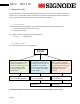
BXT 2 BXT 2-19 Example of the event readout using the service interface: As per description above, tool faults are displayed as E-numbers. Following diagram shall help to simplify the fault finding: Abort, the tool is in standby mode again Stop, the tool shuts down E10 E11 E23 Replace battery Replace battery E34 E12 E13 Release keypad Pull Rocker lever Replace keypad Replace Microswitch (Pos.103) Replace printed circuit board (Pos. 198) ak 03.
Abort, the tool is in standby mode again E35 E33 Replace the battery Let the tool cool down E21 E22 Clean mech. components E37 E38 E30 Check wirings Motor to Power electronics Abort, the tool shuts down E31 E32 E36 Check wiring PCB to power electronics.
BXT 2 BXT 2-19 5.3. Service Interface As optional accessory a data cable (Art. Nr: 1821.163.153). for detailed fault diagnosis is available. Using this data cable allows to readout the most important tool parameters on your computer and helps debugging. Hyperterminal is required as user interface. Hyper terminal is already installed on every XPComputer. For other operating systems without Hyper terminal get into contact with Orgapack. To set up Hyperterminal: 1.
BXT 2 BXT 2-19 4. Window „COM1 Properties“ will open. Make settings as enclosed in the illustration. Confirm by clicking „OK“. 5. „Debugger“ Hyper Terminal will open. Cut the connection by clicking on Icon (5). 5 6 6. File/Properties/ASCII-Setup . Check the box „Echo typed characters locally. 7. Save the settings (File/Save) and close Hyper Terminal. ak 3.
BXT 2 BXT 2-19 Establish connection: 1. Plug the data cable to the serial interface(RS 232) of your computer. Plug socket Should your PC or Laptop not be equiped with a serial interface, you for data cable have to purchase a virtual serial interface and connect via USB. Please follow the instructions of the interface manufacturer. 2. Remove the battery from the tool. Remove the screws of the motorhousing, untighten it and plug the data cable to data plug socket. 3.
BXT 2 BXT 2-19 6. Tool reset In some rare cases, it may occur that it is not possible to bring the welding unit back to its initial position Also the rocker lever is blocked. Important! Never try to lift the rocker lever with force. Reason for this behavior may be: • • • • Interrupt of power supply during welding process (disconnection of battery?!) Pulling the rocker lever with force during welding process (to protect the motor, it switches off due to over-current consumption). Microswitch (Pos.
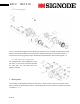
BXT 2 BXT 2-19 7. Disassembling Please consider the explosion drawing which is printed on the last pages of the operating instructions. Purpose of this manual is only to draw the technician’s attention to the most relevant issues. 7.1. Housing/electrical components Important! The connectors and cables have to be treated carefully. Never pull on the wiring to disconnect the connectors. 1. Remove the screws of the motor cover (Pos. 191) and pull it slightly backwards. 3.
BXT 2 BXT 2-19 7. Disconnect the Intermediate cable (Pos. 201). Remove the left part of the housing 8. Disconnect the motor hall sensor wirings 7.2. Welding unit 1. Remove cable tensioning (Pos. 103) 2. Remove set screw and compression spring (Pos. 86 & 169). 3. Loosen centering screws (2x Pos. 101) and remove them completely. 4. The whole welding unit can now be pulled backwards. ak 3.
BXT 2 BXT 2-19 5. Remove washer (Pos.163). To do so, retain the excentric axe (Pos.155) with a 5mm wrench on its back side and loosen the screw (Pos. 164). 6. Pull out the toothed belt wheel (Pos. 127). Remove screw (Pos.102) and retaining rings (Pos. 74). The cover of the motor support (Pos. 126) can now be removed. Important!: The motor is fixed to the motor support with precote®-coated screws.
BXT 2 BXT 2-19 7.4. Tensioning gear 1. Remove retaining ring (Pos. 136). The bevel wheel complete is now free to be pulled out. 2. Remove the tension wheel, the planetary wheels and the cam disk (Pos. 44-46 & 18) from flange complete (Pos.32). 3. Loosen the screw connection (5xPos.41) and remove retaining ring (Pos 40). All other gear parts can now easily be removed. 8. Assembly To assembly the tool, simply proceed in the opposite way.
BXT 2 BXT 2-19 9. Adjustments 9.1. Adjustment of the welding reset To avoid play in the reseting parts of the welding unit these parts can be adjusted by the set screw (pos. 73). This screw is adjusted when the tool is assembled in the factory. Normally readjustments are not necessary. When parts of this unit are replaced, it may become reasonable to check this setting. To do so proceed as follows: 1. 2. 3. 4. Unscrew (Pos 73) until it is flush with the reset cam (Pos.72).
BXT 2 20 10. BXT 2-19 Lubricating chart Recommended Lubrication: 1 2 3 4 5 6 7 8 Description: Planetary gear tensioning Planetary gear welding unit Freewheels (Pos. 127/ 132) Important! No grease! Bevel gear Cam disk, reseting cam, switching cam Tooth plate, Set screw All other moving parts. Ball guides at welding shoe, knife guide, excentric axle Lubricant: Klüber Microlube GBU-Y 131 Klüber Microlube GBU-Y 131 Universal oil e.g.
BXT 2 11. BXT 2-19 Wiring The cables must be layed very accurate. Misplaced wiring could be damaged by moving parts inside the tool. Bad connections may lead to tool malfunction. 1. Prepare the power electronics for the assembly. Connect the hall sensor cables and the signal cable to the power electronics. 2. Insert the power electronics .into the right half of the housing. Place the wires according the picture. Don’t forget the seal. 3. Mount the right half of the housing to the tool mechanics.
BXT 2 BXT 2-19 6. Secure cable (Pos. 103) with cable strap. Pay attention to strain relief to microswitch! 7. Mount intermediate cable (Pos. 201) and secure it at the retaining bracket. 8. Now the motorhousing with Printed circuit board can be mounted. Pay attention to accurate fitting at all the connections.The 2 small pins on the connectors have to fit into their counterparts. First the signal cable (Pos. 202) is connected. Best way to so is to place the tool at the edge of the table.
BXT 2 12. BXT 2-19 Error Code List 12.1. User Errors Faults in operating sequence “User errors” are no indication of a tool related defect (except defective switch). The tool calls the users attention to faulty operation. During Tensioning: Nr.
BXT 2 12.2. BXT 2-19 Device Error control system Error Reports in conjunction with the control system. Nr. E10 System error Description DEVICE_UNKNOWN_DEVICE Description: Device Type (14,4V, 18V) could not be detected Possible cause: System reaction Stop The tool is switched off. • • Wrong type of PCB (14,4 / 18V) Wrong Firmware. (The Firmware does not support this tool type. • Hardware failure when reading coding resistors Rectification: 1. Try again, unplug and plug the battery 2.
BXT 2 12.3. BXT 2-19 Device error battery Error Reports in conjunction with the battery or the motor Nr. E20 System error BATTERY_OVERTEMPERATURE Description Description: Temperature fuse of the battery. Possible cause: System reaction Stop • • • • • The tool is switched off.. Battery Temperatur >60°C Battery temperature sensor is Wiring power electronics to battery faulty Wiring power electronics to PCB faulty Temperature measurement on the power electronics is faulty.
BXT 2 E25 BXT 2-19 BATTERY_TEMPERATUR_ RESISTOR_ERROR Description: Battery temperature sensor has an invalid value. (Disconnection or short circuit) Possible cause: Stop The tool is switched off.. • • • • Battery is not plugged properly Batteries temperature sensor is faulty Wiring power electronic to contact plate is faulty Loop of temperature sensor via power electronics faulty • Resistance measurement on power electronics is faulty Rectification: 1. Plug battery properly 2.
BXT 2 E32 BXT 2-19 DRIVE_TIMEOUTERROR Description: Time out in communication with power electronics. Possible cause: • • • Power electronics is not switched on by the PCB EMV-Disorder Hardwarefailure, faulty wiring Rectification: 1. Check the wirings power electronics to PCB 2. Replace the PCB (Pos. 198) 3. Replace the power electronics (Pos 212) E33 DRIVE_OVER TEMPERATURE Description: Over-temperatur of power electronic.
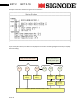
BXT 2 E38 BXT 2-19 DRIVE_HALLSENSORERR OR Description: Hallsensor failure at power electronics Possible cause: Interruption • • Current process is interrupted. Tool is in standby mode again. Motor hall-sensor defective Wiring to hall-sensors faulty Rectification: 1. Check wiring motor to power electronics 2. Replace the motor 3. Replace the power electronics (Pos 212) welding 13. tensioning Wiring diagramm: EC-Motor + Code-R NTC - ak 3.
BXT 2 14. ak 3.
BXT 2 ak 3.
BXT 2 ak 3.
BXT 2 ak 3.
BXT 2 33 15. BXT 2-19 Product information Please consider the following product information releases (status April 2011): • • • Nr.1, May 2010: • • • • • • 1. Optimised housing parts Pos. 186 2. Plug connection to welding button is no longer required (Pos. 77) 3. Firmware update (Pos. 198) 4. Plug connection to power electronics is no longer required (Pos. 212) 5. New bevel wheel (Pos. 161) 6. New Pan head screw (Pos. 54) • • • • 1. Optimized tooth plate (Pos. 53) 2. New signal cable (Pos.