Manual DoorCom IP In-Home DCIP 650-01
Contents 1 System description 3 9 Measured values 29 2 Safety remarks 3 10 Glossary 30 System conditions 3 Index 30 3 Structure DCIP 650-01 4 Autocommunication via the tele phone system with DCA 740-... 5 Terms 6 4 Components for DC IP 650-...
1 System description 2 Safety remarks System conditions: DoorCom IP In-Home Siedle DoorCom IP links the Siedle In-Home bus: Video with the IP world. Door calls are transformed via the DoorCom IP and transmitted via the IP network (Intranet) to certain PCs. The video image at the door station is converted and transmitted via the IP network. Electrical voltage The DoorCom IP Software Client is used here as a virtual in-house telephone for communication to the door station.
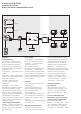
3 Structure DCIP 650-01 In-Home bus: Video Audio and video communication via IP In-Home-bus: Video BVVU 650-... BVVU 650-... IPVS 600-… TCP/IP-Network BVVU 650-... PRI 602-... USB DCIP 650-... In-Home bus link The DCIP 650-... behaves in the system in the same way as one or more bus telephones with video and is consequently bound by the same system limitations (range and number of users). The DCIP 650-... comprises the com ponents: • SIVS 610-..., system interface video server.
3 Autocommunication via the telephone system with DCA 740-... Video communication via IP In-Home-bus: Video telephone system BVVU 650-... BVVU 650-... IPVS 600-… TCP/IP-Network BVVU 650-... PRI 602-... USB place with bus programming soft ware BPS 650-... No programming is required for the DCA 740-01. For programming and configuration of the TC system, see the relevant product information and programming instructions of the manufacturer.
3 Terms Client PC user connected to a network. Full duplex Two speaking users e.g. door sta tion and remote station have an unrestricted speech connection. Open duplex communication, i.e. as opposed to the simplex speech mode. Gateway Gateways link two different sys tems and create connections across network boundaries. During this process, both the physical transmis sion modes and also protocols and addresses are adjusted accordingly.
USB The universal serial bus (USB) is a serial bus system for connection of a computer to external devices. Devices or storage media equipped with USB can be connected in run ning operation, and connected devices and their characteristics automatically detected. Vario bus Various different input and control units can be connected to the Vario bus. It comprises 4 cores. The infor mation on the Vario bus is trans mitted via the RS485 protocol.
4 Components for DC IP 650-... Bus door loudspeaker module, Bus call button module, Bus camera module BTLM 650-04 Bus door loudspeaker module for In-Home bus. Loudspeaker and microphone integrated, illuminated light button, integrated door release contact (DR) Acoustic acknowledge ment on pressing a button, can be activated if required with the BPS 650-... . contact load max.
4 Components for DC IP 650-... Input modules COM 611-02 Code lock module as an input unit for the placement of codes for con trol functions in conjunction with the Siedle Vario bus. • With keypad for making calls or • For controlling in conjunction with the Easikey controller EC 602... • C button for cancelling incorrect inputs • DR button for direct door release via the EC 602-... Operating voltage: 12 V AC Operating current: max.
4 Components for DC IP 650-... Programming, video server, DoorCom IPVS 600‑01 System interface video server Processing and adjustment of audio and video; transmission of data, audio and video to the IP network. Dimensions 118 x 88 x 48 mm DCA 740-01 DoorCom Analog DCA 740-01, in switch panel housing, can be con nected to a universal a/b interface. In conjunction with the DCIP 600/650/740-... it serves as an alternative speech connection if no speech connection via PC is preferred.
4 Components for DC IP 650-... Interfaces, power supply SIVS 610-0 System interface video server for connection of the In-Home bus: Video to IP video server. The SII 650-... is required for connection. Dimensions 144 x 130 x 55 mm SII 650-0 The system interface In-Home con verts the signals from the In-Home bus: Video for the SIVS 610-... Dimensions 107 x 89 x 60 mm VNG 602-02 Video line rectifier in a 10-grid housing. Primary: 230 V AC, 50/60 Hz Secondary: 30 V DC, 1.1 A stabi lized.
4 Software BPS 650-0 from V2.50 Bus programming software for pro gramming In-Home bus systems. For this, the programming interface PRI 602-... is also required in con junction with a BIM 650-... or the PRI 602-0 USB. DCIP SC 600-0 DoorCom IP Software Client PC programm describing a virtual in-house telephone with video on a PC monitor. Door calls with video are possible to one or more Siedle door stations. Implementing switching and control functions e.g.
5 Installation wiring diagrams Terminals DCIP 650-01 a b c Terminals and LEDs IPVS 600‑01 a 12 V DC power input for connecting the power supply b Connecting socket to the SIVS 610‑... c LED LINK lights up in green with an existing network connection d RJ45 socket ETH network connection e LED ACT lights up in orange on data transmission via the network d e f g j h Terminals and LEDs IPVS 600‑01 f Video input 1 Vss from the SIVS 610‑...
LED displays SIVS 610-0 LED signalling IPVS 600-... The IP video server IPVS 600-... has 3 LEDs which can display operating statuses and can provide an indication of possible errors: LED power on the top and the LED LINK and LED ACT on the underneath. LED Power Function OFF IPVS 600-... is switched off. Lights up in green IPVS 600-... is switched on Flashes green Access to the IPVS 600-...
LED signalling SII 650-... The system interface In-Home bus SII 650-... is fitted with 2 LEDs under the device lid which display operating statuses and provide an indication of possible faults. Switching on LED1 LED2 Function OFF ON Power On or Reset: Device boots to operating status.
5 Terminal assignment SIVS 610-0 Block diagram SIVS 610-0 G Reference for the inputs E1–E4 E4 Input 4, not used E4 Input 3, not used E4 Input 2, not used E4 Input 1, not used cvbv+ Pick off supply voltage for Vario bus, 12 V DC, max. 300 mA Da/ Db Vario bus + - Supply voltage 24-30 V DC DR DR Not used, DR via TLC 640-02 Li not used USP Not used SN1 RF signal, path SN2 SIM 740-... to SIVS 610-...
5 Terminal assignment SII 650-0 Block diagram SII 650-0 TaM/TbM In-Home bus: Video Input and output E1+/E1- Input for signalling function, 4-30 V DC or 4-20 V AC S1/S1 relay contact max.
c b TR 603-... a) Siedle Vario BCMC 650-... BTLM 650-... BTM 650-... c) Remarks L1 N c c TÖ 12 V AC min. 20 Ohm b b GND Vc Tb Ta Ta Tb Vc GND Device requirement BTM IN BTLM TaK TbK b) BVNG 650-... ZBVNG 650-... L1 N Sb Sa Tö Tö Li Li TaM TbM TaK TbK PRI 602-... USB SII 650-... Sb Sa Db Da cv bv M1 GND SN2 SN1 S1 S1 E1+ E1- TaM TbM TaM TbM VNG 602-...
In-Home bus Video Single line system Function Up to 29 PC users (Software Clients) of a network can be called from the door station. Calling, speech and door release via the Software Client DCIP SC 600-... . The Software Client must be installed on every PC which receives calls. Call functions of the Software Client 3-tone chime as standard, a dedi cated *.wav file can be assigned for each call tone. It is not possible to listen in to an existing call from other PC users in the network.
c b TR 603-... a) Siedle Vario BCMC 650-... BTLM 650-... BTM 650-... c) Remarks L1 N c c TÖ 12 V AC min. 20 Ohm b b GND Vc Tb Ta Ta Tb Vc GND Device requirement BTM IN BTLM TaK TbK b) BVNG 650-... ZBVG 650-... L1 N Sb Sa Tö Tö Li Li TaM TbM TaK TbK PRI 602-... USB SII 650-... Sb Sa Db Da cv bv M1 GND SN2 SN1 S1 S1 E1+ E1- TaM TbM TaM TbM VNG 602-...
In-Home bus Video Single-line system with DCA 740-... Function Up to 29 PC users (Software Clients) of a network can be called from the door station. Calling and door release via the Software Client DCIP SC 600-... . The Software Client must be installed on every PC which receives calls. The door call is switched via the DCA 740-... to the telephone system. A connected telephone can accept the door call. Call functions of the Software Client 3-tone chime as standard, a dedi cated *.
TR 603-... a) Siedle Vario BCMC 650-... BTLM 650-... BTM 650-... c) Remarks L1 N c c TÖ 12 V AC min. 20 Ohm b b GND Vc Tb Ta Ta Tb Vc GND b c Device requirement BTM IN BTLM TaK TbK b) BVNG 650-... ZBVNG 650-... ZBVG 650-... L1 N SbV SaV Sb Sa Tö Tö Li Li TaM TbM TaK TbK PRI 602-... USB h) SII 650-... Sb Sa Db Da cv bv M1 GND SN2 SN1 S1 S1 E1+ E1- TaM TbM TaM TbM VNG 602-...
In-Home bus Video Multiple line system Function Up to 29 PC users (Software Clients) in a network can be called per SII 650‑... . In a multiple-line system, several lines are connected. The line address must be set the same at each BVNG 650‑..., SIVS 610‑... and SII 650‑... . In each line, a maximum of one DCIP 650‑... may be used. In a multiple-line system with 2 lines, this means that 60 users can be called form a door station. Calling and door release via the Software Client DCIP SC 600‑... .
6 Commissioning DCIP 650-01 A number of steps have to be executed for commissioning the DCIP 650-... . The specified sequence must be adhered to without fail. • Prior to programming the DoorCom IP 650-... the entire In-Home system must be pro grammed and documented with the bus programming software BPS 650-... . • Complete programming of the DoorCom IP 650-... takes place using the bus programming software BPS 650-... via the SII 650-... 24 Connection of the PC to SII 650‑...
Step 3 (only with multiple line system) Manually add SII 650‑... In the BPS 650‑... , select the relevant line and add the SII 650‑... The address of BVNG 650‑..., SIVS 610‑... and SII 650‑... must be set the same. An already programmed SII 650‑... is automatically detected by the BPS 650‑... . Step 4 Create virtual users In the first table DCIP-SC (virtual users) create the users. Each user should be given a unique name wherever possible such as Secretarial. Step 5 In the tree structure of the BPS 650‑...
7 Client-Software DCIP SC 600-0 Installation of the Software Clients The Software Client DCIP SC 600-... (Ver. 1.1. or higher) must be installed on each PC which is intended to receive door calls. The Software Client communicates with the remote station, the DCIP 650-... Following the installation, the file (*.dcip) generated by the bus pro gramming software BPS 650-... must be imported. The addresses to which the client is intended to respond are selected from the imported file.
Possible error sources • No speech connection from the PC to the door. The microphone amplifier may not be activated. • Installation must take place as administrator, so that all registered users have access to the Software Client later. • Marked echo on the line in speech mode. In the Windows volume regulation for sound reproduction, Sound off must be activated under the microphone controller. This selection prevents the PC microphone signal being reproduced in the PC loudspeaker.
7 DoorCom DCA 740-01 8 DoorCom IP Factory setting IPVS 600-... The DoorCom Analog DCA 740-... is used as an interface between DoorCom IP and an analog tel ephone connection of a telecommu nication system. With the reset button at the IPVS 600‑..., it can be reset to the as-delivered status. It is essential to load the Siedle factory configuration in the IPVS 600‑... after a reset. Proceed as follows. 1 Start the Internet Explorer on the PC and enter the following in the address line: http://192.168.0.
9 Measured values Measurement values for DoorCom IP, to be measured using a digital multimeter Idle status min. Voltage +/ at the SIVS 610-... 24 V DC Current consumption max. 30 V DC 500 mA Conductor lengths VNG 602-... supplies 1 DCIP 650-... 100 m VNG 602-... supplies 2 DCIP 650-...
10 Glossary Index As-delivered status 29 Block diagram 18 Client 26 Commissioning 24 Config 24 DoorCom 10 Factory setting 29 IP 6 IP address 6 IWA 6 LED display 15 Licences 26 Line rectifier 12 Power supply 4, 6 Programming 24 Server 8 Software Client 26 Subnet mask 6 System interface video server 15 System requirements 2, 26 TCP 6 Terminals 14 Wiring diagram 18 BTLM 650-04 BTM 650-... BCMC 650-... BPS 650-0 BVNG 650-... COM 611-... DCA 740-... DCIP SC 600-0 DRM 611-... IPVS 600-... PRI 602-...
S. Siedle & Söhne Telefon- und Telegrafenwerke OHG Postfach 1155 78113 Furtwangen Bregstraße 1 78120 Furtwangen Telefon +49 7723 63-0 Telefax +49 7723 63-300 www.siedle.de info@siedle.de © 2008/07.12 Printed in Germany Best. Nr.