
Programming instructions


21
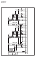
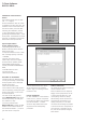
In-Home bus Video
Single-line system with DCA 740-...
Function
Up to 29 PC users (Software Clients)
of a network can be called from
the door station. Calling and door
release via the Software Client
DCIP SC 600-... .
The Software Client must be
installed on every PC which receives
calls. The door call is switched via
the DCA 740-... to the telephone
system. A connected telephone can
accept the door call.
Call functions of the Software Client
3-tone chime as standard, a dedi-
cated *.wav le can be assigned for
each call tone.
It is not possible to listen in to an
existing call from other PC users in
the network. The door is opened by
the called PC user using a “virtual
door release button”, the light
switching function is actuated using
a “virtual light button”. The door
call can be muted with an optical
display on the monitor.
Supplementary functions
• Additional PC users can be imple-
mented with an additional line.
• Up to 10 PC users can be called in
parallel with a call button from the
door station. Up to 49/45 PC users
are possible at one IPVS 600-... .
Reduction to 45 PC users can result
if 10 or more PC users are cong-
ured as parallel devices.
Remarks
a) The TR603-... (12VAC, 1.3A)
can supply 1door release button
and max.24bus call button modules
with LED lighting (BTM650-01, -02,
-03 and -04).
With more than 24illuminated bus
call button modules, an additional
TR603-... is required. Current
consumers in the AS diagram:
Door release appr. 600mA
Camera heating 100mA
LED lighting
Per bus call button module 25mA
b) Door release contact load in the
bus video line rectifier BVNG650-...
max. 15 V AC, 30VDC, 2A.
• Light contact load in the bus video
line rectifier max. 15 V AC, 30VDC,
2A.
c) Door release 12 V AC, use at least
20Ohm (e.g. TÖ615-...).
d) Conductor length bus telephone -
storey call button ERT max. 50 m.
e) When using the internal video
memory module, the bus telephone
BTCV850-... must be supplied
by an additional direct voltage
(20-30VDC, 350mA). NG602-...
or VNG602-... can be used for this
purpose. Connection of the power
supply to terminals +M/-M.
f) Distance of the BVNG650-.../
SII650-... to the door station max.
100 m with J-Y(ST)Y 0.8 mm core
material. During installation, ensure
that the door release is laid in a
separate cable. Supply voltage
available from SIVS610-... at the
terminals bv+/cv- 12 V DC, max.
300 mA.
The DCA740-01 can optionally be
connected to the PBX extension of
a telephone system. Active door
calls can then be routed via the
telephone. The functions of the
IPinterface still remain possible.