EPP2000 and ISA2000 Fiber Optic Spectrometer Manual 14390 Carlson Circle, Tampa, FL 34677 Phone 813-855-8687 fax 813-855-2279 email: info@StellarNet-Inc.com web: www.StellarNet-Inc.
CC Declaration of Conformity According to EN45014 We StellarNet, Inc.
Fiber Optic Spectrometer Manual Introduction______________________________________________________ Quick Start Installation______________________________________________ EPP2000 Hardware Interface_________________________________________ Connector Interface Signals____________________________________ Special Interface Signals_______________________________________ Unit Address Selector_________________________________________ Power requirements___________________________________________ ISA2000 address and
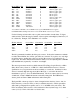
Model EPP or ISA Wavelength range Resolution g/mm Grating 2000C-UV+VIS* 2000UV 2000UV2 2000UV3 2000VIS 2000NIR 2000NIR2 2000NIR2b 2000NIR3 2000NIR3b 2000NIR4 2000NIR4b 2000XNIR2 200-850nm 200-600nm 200-400nm 220-350nm 350-1150nm 500-1100nm 600-1000nm 785-1200nm 550-840nm 680-935nm 500-700nm 600-800nm 1200-1600nm 0.
Quick Installation for SpectraWiz Software Summary Installation for USB2EPP cable on Win98/ME/00/XP 1. If required, install adapter to add USB-2 ports. Cable will run 40x slower on USB-1 port. >> Please note: software drivers should be installed before inserting adapter hardware. Grab the driver CD from USB-2 adapter box and follow the manufacturers instructions. Note: for Mercury brand adapters (VIA USB 2.0 drivers) run “setup.exe” on CD path = "\USB\USB20_NEC\PC_Driver\setup.exe".
Installation for Win95/Win98/WinME Non-Plug-and-Play Interfaces The ISA2000 plug-in spectrometer and the EPP-ISA parallel port card from SIIG require switches to be set for the port address and IRQ interrupt request selection, so you will first need to find what is available in your computer using the Windows Device Manager. Change the ISA interface switches to an available IRQ and port address by changing its jumpers then install the card into your computer.
Using the BIOS menus provided, change the port mode to EPP or EPP+ECP. Please note the mode cannot be set to the ECP only mode (or any other selection such as SPP, Bi-directional, or Standard), as these will not work. If you cannot find an EPP mode selection, the EPP2000 will not work. An EPP-PCI or EPP-PCMCIA card is needed. Using the BIOS menu, verify the LPT port address (normally 378 hex). Later, set the SpectraWiz Setup => Interface port configuration to the same port address.
mode (The ECP mode is the Enhanced Capabilities Port mode and is the “Cadillac” mode) or it just doesn’t work perfectly like it should. We recommend using the new USB2EPP cable for best performance via USB-2 ports. Otherwise a second parallel port should be installed for the EPP2000 spectrometer(s). These are the EPP-PCI for desktops or EPP-PCMCIA for notebooks.
EPP2000 Special Interface Signals The above DB25 computer interface connector contains user defined signals specific for the EPP2000 spectrometer on pin 12, 13, and 15. Any of these signals can be mounted to rear panel jacks via special request. Pin 12 is an EPP2000 spectrometer output to indicate start of scan. This may be tied to a XENON strobe lamp’s trigger input to flash the lamp at the beginning of each scan.
An optional Battery Power unit (BP1) is available for the EPP2000. It contains a 2.4 amp hour rating which will power the spectrometer for about 8 hours. The BP1 includes a +12VDC wall transformer to re-charge the battery. ISA2000 Hardware Switch Selections The base address for the spectrometer plug-in card is selected with 4 slide switches at location U68 (just above U43). The board may be place at 16 different locations from 300 hex – 3F0 hex. using the following address switch configurations.
SpectraWiz Software General Help //////////////////////////////////////////////////////////////// Experiment Procedures.."how to get started taking data" ToolBar Icons..........areas on the screen for mouse operation System Indicators......show you what's on/off at a glance //////////////////////////////////////////////////////////////// Experiment Procedures ////////////////////////////////////////// Ensure that you have installed the calibration coefficients for your unit.
reflectance, using a fiber probe, hold at 45 deg to your white standard about 1/4 inch away. For cuvette holders, use cuvette in place with no sample. For dip probes, use your solvent solution for reference. The curve MUST NOT touch the top of the graph. If the slider bar on the toolbar is already max (for fastest detector integration rate), then you must reduce the input signal by using a smaller fiber or insert a filter. For reflectance, just move the tip back from the white standard (reference) surface.
sample Same as menu File->Save->Sample (to disk) Save dark spectrum [picture of DARK light bulb] Used for Absorbance, Transmittance, and Irradiance modes. Left Click here with light off. Caution: Right Click will zero previous dark. Save reference spectrum [picture of YELLOW light bulb] Used for Absorbance and Transmittance modes. Left Click here with light on and without sample in place. When viewing Irradiance -> watts per square meter, clicking here starts the UV monitor application.
>> Centbase = level used to compute AreaPSD & Centroid. 2. Use right click to start dual cursor measurement for: AreaPSD, Width, Base (via user positioned cursors) a. Position data cursor to right of area to measure, using right click on graph at desired location. b. Then right click Area toolbar icon and this will change the data cursor to a dashed line. c. Now position a second data cursor to left of area at desired location on graph with right click. d.
SpectraWiz File Menu ////////////////////////////////////////////////////////////////// Save...................current spectra sample data to disk file Open...................spectra file for graph display & print Print Setup............allows page layout selections for graph Print..................current graph sample data to print device Exit...................
When multiple channels are enabled, a file -> save -> sample -> automatically saves all channels. This occurs ONLY when the VIEW -> Multi-Graphs has first been enabled. Each channel will then append its channel number. For example if the file name to save is given as TEST and you are in absorbance view, then the files for a 3 channels configuration will be saved as Test1.abs, Test2.abs, and Test3.abs.
SpectraWiz Setup Menu /////////////////////////////////////////////////////////////////// Detector integration time....sets new detector integration period Number of scans to average...Y axis smoothing improving sig2noise Spectral smoothing controls..X axis smoothing improving sig2noise Temperature compensation.....periodic baseline shift compensation XTiming resolution control...selects modes for Standard/Extended Episodic Data capture........collect spectral data over time Optical Trigger..............
Spectral smoothing algorithm that avoids crushing peaks. published in Analytical Chemistry - July 1964. First Display Persistance level 0..9 This controls smoothing for digital readout displays using exponentially smoothed averaging. For example, spectral data is used to compute the ChemWiz concentration for selected methods. Average dark baseline: checked=ON This controls the baseline average level to keep it above zero.
Episodic data capture can be combined with the optical trigger function. First setup the trigger to operate in continuous mode at the desired wavelength and trigger level as a percent of scale, then start the Episodic data capture. The system will capture events pre-qualified by the trigger level. You can select a specific number of events to record or allow it to record until terminated by the operator.
Map Logical to physical: If you have multiple spectrometers this provides a setup. This allows setup of the LU (Logical Unit) to physical unit address. A similar input is made under the Setup->Unit menu, however this selection does not deal with the coefficients. A cross check is also made to determine if multiple LU's have the same physical address. Each system must have at least 1 but only 1 unit at physical address 1. The system can handle LU's 1-8 with physical addresses 1-8.
Use this option to tell the SpectraWiz software where the new hardware interface has been set. Once the new port has been selected from the menu the Windows registry is updated. An option box for the LAVA PCI adapter appears on this panel (EPP-PCI card). Check the LAVA box if this is the interface that you have installed (and NOT if your using the Quatech SPP-100 (EPP-PCMCIA card) or the computers integrated printer port).
SpectraWiz View Menu ////////////////////////////////////////////////////////////////// Scope mode.............displays uncompensated spectral data Absorbance mode........display requires dark & reference for AU Transmission mode......display requires dark & reference for %T also used for reflectance measurements Irradiance mode........display Watts,Micro-Watts,Lumens,Moles,fc Ref spectra............display of reference spectra minus dark Channel................
reflection and is used for reflectance applications. Use transmission mode for SpectroColorimetry. Use a white light to reflect off of a white surface. Save this as the reference. Then replace the white standard with a color sample to measure. You will then see the spectral shape for the color where the white standard displays as a straight line at 100 percent.
Setup range for watt and Rflux measurements: Specify the start and end wavelengths for the range computation of the total power. The default range is 400-700nm. ////////////////////////////////////////////////////////////////// View -> Ref spectra: Displays the reference and dark data previously saved as ref(n)-dark(n). This is useful for troubleshooting absorbance or transmission applications. The Ref spectra must not be clipped at its peaks, indicating a bad reference.
////////////////////////////////////////////////////////////////// View -> Zoom: ON/OFF Allows a selected region to be expanded to a full graph. This option will work for any view mode. You are prompted for X-axis left and right wavelength and Y-axis top and bottom. Selecting a bottom as a negative value allows proper viewing for differential displays. The Y zoom also can enabled by by right clicking on the Z button for mouse XY zoom described below.
SpectraWiz Applications Menu ///////////////////// Applications ///////////////////////////// CIE Color Monitor............for ChemWiz Methods..............for Ultra Violet Monitor.........for Irradiance Calibration.......
Pixel smoothing Temperature compensation = level 4 = ON Prior to enabling the colorimeter ensure that you have saved a dark reference and a white reference (such as with the RS50 white standard)while in the Scope Mode. This ensures that your spectrometer is performing correctly with NO light and White light using your reflectance probe or integrating sphere.
drift correction. A "ChemData.log" file allows users to quickly save samples for later viewing or printing. //////////////////////////////////////////////////////////////// UV Monitor ////////// This application is also started when the user has selected View->Irradiance->watts per square meter AND then clicks on the yellow light bulb icon. The spectrometer needs to have a proper irradiance calibration for the UV range from 200-400nm. Both U.S. FDA or Spanish UV health standards can be displayed.
9-328nm -> 1 * power(0.094 * (298-nm)) 329-400nm -> 1 * power(0.015 * (139-nm)) A "UVdata.log" file allows users to quickly save monitor display results for later viewing or printing. //////////////////////////////////////////////////////////////// Irradiance Calibration ////////////////////// This application allows users to perform irradiance calibrations in the field. It requires a calibrated source lamp from 300 to 1100nm or from 300 to 800nm.
Photo Diode Array - Application Note StellarNet spectrometers (EPP2000, EPP2000C, and ISA2000 models) equipped with a Toshiba PDA (Photo Diode Array) operate differently in the XTiming resolution modes, which can be selected from the Setup menu. Low resolution (fastest) - provides two spectral traces in a single display.
Technical Support Bulletin, 11/17/99 Our software engineers have found a problem in the InstallShield program that prevents a key and its data values from being written into the WindowsNT registry. This data is needed to prevent WindowsNT from acquiring an LPT2 printer interface for use as its own device. An alternative to the following fix is to disable ALL printing. The following fix will get SpectraWiz and its associated WinRT driver operational and allow printing on LPT1.
- 32 -