DisplayPort to CAT5e Daisy Chain HD Extender Kit with RS-232 & IR Installation Guide Introduction The DisplayPort to CAT5e Daisy Chain HD Extender Kit with RS-232 & IR extends DisplayPort signal over one Cat5/6 cable up to 330ft and is cascade connection supported.
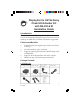
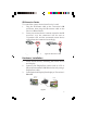
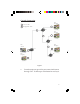
CE-DP0611-S1 Layout Transmitter Unit (Tx) Figure 1: Transmitter side panel • • 2 DC 5V: DC 5V power jack. Plug the included power adapter here PWR: LED indicator for power status.
• • • • • • • • LINK: LED indicator for link status. On when the connection of Transmitter and Receiver is established and detected DP IN: DisplayPort signal input port. Connect this port to your DisplayPort source device by using a DisplayPort cable (not included) DP OUT: DisplayPort signal output port. Connect this port to a local DisplayPort display by using a DisplayPort cable (not included) : Audio output port. Connect to the a local 3.
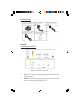
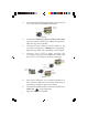
• • • • • • • • • 4 DC 5V: DC 5V power jack. Plug the included power adapter here IR: Connect to the included IR receiver cable RESET: Use the fine end of any object to press and hold the bottom to return to default settings PWR: LED indicator for power status. On/Off when the Receiver is powered on/off LINK: LED indicator for link status. On when the connection of Transmitter and Receiver/Repeater is established and detected RS-232: RS-232 control port. Plug the included 3.
IR Extension Cables To control the source device from Receiver's end: 1. Plug the IR blaster cable to the Transmitter's IR connector, then plug the IR receiver cable to the Receiver's IR connector. 2. Point your source device's remote control to the IR receiver's eye, the command will be sent to Transmitter end, and the connected source device will enforce the command accordingly. Figure 3a: IR blaster cable Figure 3b: IR receiver cable Hardware Installation 1. 2. 3.
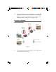
4. Connect remote DisplayPort display (such as a LCD TV) to the receiver's DP OUT connector. output display Figure 5 5. 6. 7. Connect the IR blaster cable and IR receiver cable to the Transmitter and Receiver's IR ports separately. Skip this step if not needed. Connect the two 3.5mm to RS-232 cables to the Transmitter and Receiver's RS-232 ports separately. Skip this step if RS-232 controlling is not needed. Connect your CAT5/6 cable between the Transmitter's and Receiver's LINE port.
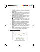
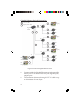
10. Plug the included power adapters into the DC 5V power jack of the Transmitter and Receiver separately. Power on the connected source device and display(s), the Extender kit is ready for use. Function Diagram Basic connection IR receiver cable (optional) remote DP display IR blaster cable (optional) 2 DP source 1 2 local DP display 2 1 CAT. X cable 2 DisplayPort cable Figure 7 • The extension distance through CAT.
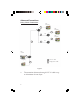
Advanced Connections Daisy Chain Connection DP Display 2 DP Display Rx 2 1 Rx DP Display 2 1 1 Rx DP source 2 DP Display 2 1 CAT. X cable 2 DisplayPort cable Figure 8 • 8 The extension distance through CAT.
Cascade Connection 1 CAT. X cable 2 DisplayPort cable DP Display 2 1 Rx DP Display 2 1 Rx DP source DP Display 1 2 2 Tx DP Display Rx 2 Figure 9 • Cascade receivers up to 10 layers; extension distance through CAT.
Gigabit Ethernet Switch Connection 1 CAT. X cable 2 DisplayPort cable 2 1 Rx Gigabit switch 1 DP Display 1 1 Rx 1 Rx 2 DP Display 1 Rx 1 Rx Rx 1 2 DP Display Rx Tx 2 DP source 1 1 DP Display Rx Rx 2 Figure 10: Used with Gigabit Ethernet switch • • 10 Connect with the Gigabit Ethernet switch especially when your Tx or Rx unit has only one signal input/ output port The extension distance through CAT.
Technical Support and Warranty QUESTIONS? SIIG’ s Online Support has answers! Simply visit our web site at www.siig.com and click Support. Our online support database is updated daily with new drivers and solutions. Answers to your questions could be just a few clicks away. You can also submit questions online and a technical support analyst will promptly respond. SIIG offers a 2-year manufacturer warranty with this product.
About SIIG, Inc. Founded in 1985, SIIG, Inc. is a leading manufacturer of IT connectivity solutions (including Serial ATA and Ultra ATA Controllers, FireWire, USB, and legacy I/O adapters) that bridge the connection between Desktop/ Notebook systems and external peripherals. SIIG continues to grow by adding A/V and Digital Signage connectivity solutions to our extensive portfolio.