
Installation guide


3
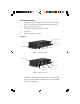
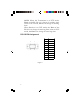
• HDMI OUT: HDMI signal output port. Connect this
port to your HDMI display by using an HDMI cable
(not included)
• Ethernet: Connect your Ethernet cable here to
establish an extended network connection
• Power jack: Plug the included power adapter here
• Power LED: On when power adapter is connected
Figure 3: Transmitter & Receiver_Front
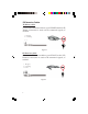
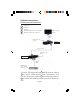
RS-232
DIP switch
RJ45
Link status
LED
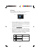
• DIP switch: Switch the DIP switch to change the
mode between RS-232 Operation mode for normal
data transfer and firmware update mode
• RS-232: Connect to a serial port device or computer
here for normal data transferring or for firmware
update, if needed. Refer to DIP Switch section on
next page for further information
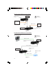
• HDBASET: HDMI signal output port for Transmitter;
HDMI signal input port for Receiver. Connect your
Transmitter's and Receiver's HDBASET ports by
using an RJ45 cable (not included)
• Link status LED: On when HDBASET connection is
established