
Installation guide

4
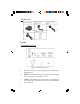
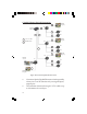
• PWR: LED indicator for power status. On/Off when
the Receiver/Repeater is powered on/off
• LINK: LED indicator for link status. On when the
connection of Transmitter and Receiver is established
and detected
• RS-232: RS-232 control port. Plug the included
3.5mm to RS-232 cable then an RS-232 cable here, if
needed
• HDMI OUT: HDMI signal output port. Connect
this port to the remote HDMI display by using an
HDMI cable (not included)
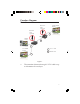
• LINE 1-3: Signal input port, connected with
Transmitter's LINE port by using a CAT X cable (not
included).
Either one port is connected to the Transmitter unit,
the other two ports could be connected to other
Receivers/Repeaters for further signal extension or
expansion. See the Function Diagram section on
page 7-10 for more details
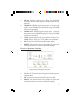
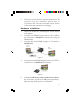
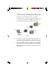
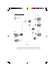
IR Extension Cables
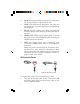
To control the source device from Receiver's end:
1. Plug the IR blaster cable to the Transmitter's IR
connector, then plug the IR receiver cable to the
Receiver's IR connector.
Figure 3a: IR blaster cable Figure 3b: IR receiver cable