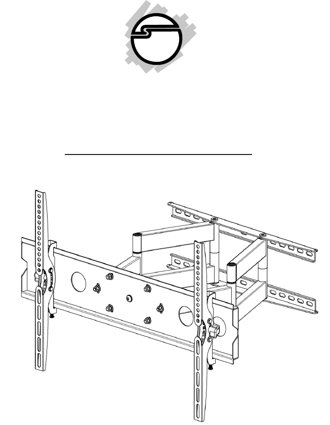
Large Full-Motion TV Wall Mount Installation Guide Articulating Full-Motion Universal Flat-Panel TV Wall-Mount TV size: 42" to 80" Tilt angle: 10 degrees up / 15 degrees down Max load capacity: 154 lbs Wall distance (at the front plate): 3.75" to 17.35" Important: If you have difficulty following or understanding these installation instructions, please consult a qualified installation specialist.
Caution • • • • • • • • • • • • Prior to installation of this product, the installation guide should be read and completely understood. The installation guide must be read to prevent personal injury and property damage. Keep the installation guide in an easily accessible location for future reference. This mount contains small parts which can act as a choking hazard if swallowed. CAUTION: The maximum load capacity is 154 lbs.
Hardware Kit a (x1) Wall plate c b (x1) Left monitor bracket (x1) Right monitor bracket e f g h (x4) M4x12 bolt (x4) M5x12 bolt (x4) M6x12 bolt (x4) M8x16 bolt i j k l (x4) M4x30 bolt (x4) M5x30 bolt (x4) M6x35 bolt (x4) M8x40 bolt m n o p (x4) M4 lock washer (x4) M5 lock washer (x4) M6 lock washer (x4) M8 lock washer q r s t (x4) M6/M8 spacer (x8) M4/M5 washer (x4) M6/M8 washer x y (x6) Concrete anchor (x1) Bubble level (x4) M4/M5 spacer v (x6) Lag bolt w (x6) La
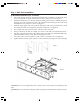
Step 1: Wall Plate Installation A) Wood Stud Installation (16" on center) 1. 2. 3. 4. 5. 6. 7. 8. Use a high quality electronic stud finder (commercially available) to locate dead center of two wood studs 16" apart and mark the location with a pencil. See Figure 1. Mount the bubble level (y) onto the wall plate at the position shown. With the help of an assistant, place the wall plate onto the wall in the desired mounting location and check the bubble level to ensure it is level. See Figure 2.
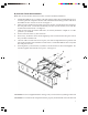
B) Concrete / Brick Wall Installation Note: The concrete anchors must be used for concrete and brick installation. 1. 2. 3. 4. 5. 6. 7. Mount the bubble level (y) onto the wall plate at the position shown. With the help of an assistant, place the wall plate onto the wall in the desired mounting location and check the bubble level to ensure it is level. See Figure 3. Mark six holes, minimum of 6 inches apart, to be used for securing the mount, and place the wall plate aside.
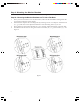
Step 2: Mounting the Monitor Brackets The hardware kit includes bolts of various diameters and lengths to ensure optimal installation. Step 2A - Mounting the Monitor Brackets to a TV with a Flat Back 1. 2. 3. 4. Place your TV screen down on a soft, flat surface, and locate the threaded mounting holes that are located on the back of the display. Determine the depth of the mounting holes by inserting a straw or toothpick.
Step 2B - Mounting the Monitor Brackets to a TV with a Curved Back 1. 2. 3. 4. Place your TV screen down on a soft, flat surface, and locate the threaded mounting holes that are located on the back of the display. Determine the depth of the mounting holes by inserting a straw or toothpick. Select the bolt (i, j, k, l) with the correct depth and diameter of the mounting holes of your TV. Please make sure the monitor brackets (b, c) are vertically centered and level with each other.
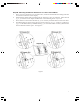
Step 3: Attaching the TV to the Wall Plate Warning: Some TVs may require two people to lift and position it onto the wall plate. SIIG, Inc. is NOT RESPONSIBLE for any damage or injury caused by incorrect installation, assembly or use. 1. 2. Hang the TV with monitor bracket (b,c) assembly onto the top of the wall plate (a) then let the bottom of the monitor brackets rotate to the bottom of the wall plate. See Figure 6.
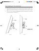
Step 4: Tilt Adjustment 1. Loosen the tilt adjustment knobs (on each monitor bracket), tilt the TV to the optimal viewing angle, then re-tighten the knobs to secure the tilt angle. See Figure 8.
Step 5: Leveling the TV If needed, the TV can be leveled after it has been mounted to the wall mount by rotating the front plate that the TV mounts onto. To make this adjustment, first unmount the TV from the front plate, then loosen the six bolts (located on the front of the front plate) and carefully rotate to the left or right to the desired postion. Retighten the six bolts, then re-mount the TV to the front plate. See Figure 9.
Blank Page 11
Technical Support and Warranty QUESTIONS? SIIG’s Online Support has answers! Simply visit our web site at www.siig.com and click Support. Our online support database is updated daily with new drivers and solutions. Answers to your questions could be just a few clicks away. You can also submit questions online and a technical support analysts will promptly respond. SIIG offers a 3-year manufacturer warranty with this product.