
Installation guide

2
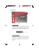
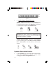
Layout
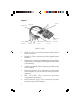
Figure 1: Layout
Digital In
• LINE In: This connector provides analog stereo
line-in function
• Digital In: This connector provides digital input
function
• Digital Out: Connect to digital input of an external
audio device via Digital S/PDIF optical cable (cable
not included)
• Center Out (yellow): This connector provides center
audio output
• Front Out (green): This connector provides front
audio output, or you can connect one set of stereo
speakers
• MIC IN (red): This connector provides
microphone-in function
• Back Surround (grey): This connector provides
back surround sound output
Digital Out
Line In
Center
(yellow)
Front
(green)
MIC
(red)
Back surround
(grey)
Surround
(black)
Front panel
audio
connector