eSATA II PCIe Pro RAID Quick Installation Guide Introducing the eSATA II PCIe Pro RAID The eSATA II PCIe Pro RAID is an ultra high-speed two channel Serial ATA Generation II RAID controller for use in PCI Express enabled systems. Features and Benefits • • • • • • • Compliant with PCI Express Base Specification 1.0a Compliant with Serial ATA 1.
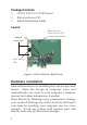
Package Contents • • • eSATA II PCIe Pro RAID board Driver software CD Quick Installation Guide Layout HDD LED pins (Front chassis LED; connects horizontally) External connectors HDD Activity LED Figure 1. eSATA II PCIe Pro RAID layout Hardware Installation General instructions for installing the card are provided below. Since the design of computer cases and motherboards vary, refer to your computer’s reference manual for further information, if needed.
1. 2. 3. 4. 5. 6. 7. Turn OFF the power to your computer and any other connected peripheral device. Unplug the power cord from the back of the computer. Remove your computer cover. Remove the slot bracket from an available PCI Express slot. To install the card, carefully align the card's bus connector with the selected PCI Express slot on the motherboard. Push the board down firmly, but gently, until it is well seated. Replace the slot bracket holding screw to secure the card.
RAID Arrays RAID Arrays are setup in the eSATA II PCIe Pro RAID BIOS. Table of Contents RAID 0 (Striping) ............................................ page 4-5 RAID 1 (Mirror) .............................................. page 5-6 Single Drive Setup (Contiguous) .................... page 7 JBOD Drive Setup (Concatenated) .............. page 7-8 Rebuilding a Failed Mirror Set .................... page 8-9 Deleting RAID Arrays ...................................... page 9 Resolving Conflicts ................
6. 7. 8. 9. When asked Are You Sure (Y/N)?, press Y to accept. Press Ctrl+E to exit the BIOS. When asked Are you sure to exit (Y/N)?, press Y to exit and reboot. Continue with Fdisk and Format steps as if you were installing a conventional hard drive. Manual Configuration 1. As the BIOS boots press Ctrl+S or F4 when prompted to enter the RAID BIOS. 2. At the next screen select Create RAID Set, then press Enter. 3. Select RAID0, then press Enter. 4. Select Manual configuration, then press Enter. 5.
2. 3. 4. 5. 6. 7. 8. 9. At the next screen select Create RAID Set, then press Enter. At the next screen select RAID1, then press Enter. Select Auto configuration, then press Enter. Input the RAID size, then press Enter. When asked Are You Sure (Y/N)?, press Y to accept. Press Ctrl+E to exit the BIOS. When asked Are you sure to exit (Y/N)?, press Y to exit and reboot. Continue with Fdisk and Format steps as if you were installing a conventional hard drive. For Existing Hard Drives with Data 1.
Single Drive Setup Setting up your hard drive to operate as a single drive may destroy all existing data on your hard drive, therefore, back up any data on your hard drive before connecting it to the raid controller or use a blank or new hard drive. 1. 2. 3. 4. 5. 6. As the BIOS boots press Ctrl+S or F4 when prompted to enter the RAID BIOS. At the next screen select Create RAID Set, then press Enter. Select Concatenation, then press Enter. Select 1, then press Enter.
2. 3. 4. 5. 6. 7. At the next screen select Create RAID Set, then press Enter. Select Concatenation, then press Enter. Select 2, then press Enter. Select one hard disk drive, then press Enter. Select the second hard disk drive, then press Enter. When asked Are You Sure (Y/N)?, press Y to accept. Note: In the RAID BIOS screen, under Logical Drive, SiI Concatenation and the size of the logical drive will appear. 8. 9. Press Ctrl+E to exit the BIOS.
6. Input the RAID size, press Enter. When asked Are You Sure (Y/N)?, press Y to confirm. 7. Select Rebuild Raid 1 Set, press Enter. 8. When asked Are you sure (Y/N)?, press Y confirm. The mirror will begin rebuilding. Do not interfere with the process. 9. When rebuilding is finished, press Ctrl+E. 10. When asked Are you sure to exit (Y/N)?, press Y to exit and reboot. For Online Mirror Rebuild (in Windows) 1. Replace the failed drive with one of equal or greater capacity, then start the computer. 2.
Resolving Conflicts When a RAID set is created, the metadata written to the disk includes drive connection information. If, after a disk failure, the replacement disk was previously part of a RAID set (or used in another system), it may have conflicting metadata. If so, this will prohibit the RAID set from being either created or rebuilt, in order for the RAID set to function properly, this old metadata must be first overwritten with the new metadata.
Driver Installation This section provides information on how to install the eSATA II PCIe Pro RAID drivers. Windows 2000 For A New Installation A new installation of Windows 2000 requires a floppy disk for the driver installation. To make this floppy disk, copy the contents of the 32bit folder, found on the driver CD, onto a blank floppy disk then follow the directions below. 1. 2. 3. 4. 5. 6. 7. Setup the RAID array prior to Windows installation. Follow Windows 2000 installation procedure.
4. 5. 6. Insert the driver CD, check CD-ROM drives, uncheck the other boxes, click Next, click Next again, then click Finish. Repeat steps 2-4. Restart Windows to complete the installation. When Windows resumes, go to SATARaid5 GUI on page 16 and install the RAID utility. 32-bit Windows XP/Server 2003 For A New Installation A new installation requires a floppy disk for the driver installation.
For An Existing Installation 1. Setup the RAID array prior to driver installation and boot up to Windows. 2. At the Found New Hardware Wizard: XP (w/SP1 or earlier)/Server 2003: continue to step #3. XP (w/SP2 or later)/Server 2003 (w/ SP1 or later): select No, not at this time, then click Next. 3. Insert the driver CD, select Install the software automatically (Recommended), and click Next. 4. Click Finish to complete the driver installation.
8. Press Enter to finish driver installation, then follow the on-screen instructions to complete Windows installation. When Windows installation completes, go to SATARaid5 GUI on page 16 and install the RAID utility. For An Existing Installation 1. Setup the RAID array prior to driver installation and boot up to Windows. 2.
Windows Vista™ For A New Installation 1. Setup the RAID array prior to Windows installation. 2. Follow Windows installation procedure. 3. At Where do you want to install Windows?, click Load Drivers. 4. Insert the driver CD, click Browse. 5. Double click your CD-ROM drive: For 32-bit Windows Vista: select 32bit, then click OK. For 64-bit Windows Vista: select 64bit, then click OK. 6. Select Silicon Image SiI 3132 SoftRaid5 Controller..., then click Next. 7.
SATARaid5 GUI The SATARaid5 GUI provides the user an easy way to monitor your RAID set. SATARaid5 GUI Installation Important: Windows 2000 SP4 or later is required for installation. 1. 2. 3. Insert the driver installation CD. At the Windows desktop click Start: For 2000: Click Run, type D:\gui\setup2000.msi, then click OK. (Change D: to match your CD-ROM drive letter) For Windows XP/Server 2003: Click Run, type D:\gui\setup.msi, then click OK.
RAID Groups window Device Configuration window RAID Groups window This window identifies SATA host adapters and configured RAID groups. Selecting each RAID group in the RAID Groups window, members consisting of the RAID group will be highlighted in the Device Configuration window. Right clicking on each node in the RAID Groups window, a popup menu will be displayed to let the user select an action to be performed for the selected controller or RAID group.
SATARAID 5 Configuration Menu SATARAID5 configuration menu includes customization of the settings for Log File, Popup and Advanced Options. By clicking on File, then Configuration, the user may customize the settings for Log File, Popup and Advanced Options tabs. Log File The log file is used to store event information received from all the RAID drivers. The log file can be viewed with any text viewer (such as Notepad) or with the Event Log window of SATARAID5 GUI.
Popup The popup window is a visual notification that an event has occurred. The popup window can be disabled or set to popup for only certain event levels.
Advanced RAID Features: When this feature is selected and the user selects to create RAID group, if the RAID group to be created is fault tolerant group (RAID1), the user will be able to select Improper Shutdown Policy in the Create RAID Group dialog box. The Advanced RAID Features are not supported for Legacy RAID groups. Resources Info Support: When this feature is selected, Resources menu item will be available under the Window menu. This feature is for debugging purpose only.
Device Summary This command displays the Segment Summary window to show all physical devices' segments. RAID Group Menu Command Create RAID Group This command displays a dialog box to let user create a RAID group, the user needs to specify the following parameters: RAID Group Label: Provides a name for the RAID group. RAID Group: Select a group ID from the available ID list.
RAID Group Summary This command displays a dialog box to show all RAID groups' group ID, configuration and status. The RAID Group Summary window has it's own menu bar. All options available via the menu bar are shown below. Sorting: This command displays a dialog box to let the user choose up to 3 items to sort RAID group items in the RAID Group Summary window. Fields: This command displays a dialog box to let the user choose which fields will be shown in the RAID Group Summary window.
Resume: This command allows the user to resume the suspended task items. Cancel: This command allows the user to cancel the selected task items. Delete: This command displays a dialog box to let the user delete the selected task items. Event Log This command displays the Event Log window. The Event Log window displays SATA device-related events that occur while SATARAID5 GUI is running. The Event Log window has it's own menu bar. All options available via the menu bar are shown below.
Capacity: Select from a list of RAID group sizes. Chunk Size: Select one value from the available list. Rebuild Priority: Select from the available list. RAID 0 and virtual disk do not require this. 10 is the highest level of rebuild priority which means that rebuild times will be faster but will take more CPU resources to rebuild. Devices: Select RAID member devices from the available device segment list.
Blank Page 25
Blank Page 26
Technical Support and Warranty QUESTIONS? SIIG’s Online Support has answers! Simply visit our web site at www.siig.com and click Support. Our online support database is updated daily with new drivers and solutions. Answers to your questions could be just a few clicks away. You can also submit questions online and a technical support analysts will promptly respond. SIIG offers a lifetime manufacturer warranty with this product. Please see our web site for more warranty details.
About SIIG, Inc. Founded in 1985, SIIG, Inc. is a leading computer upgrade manufacturer of I/O connectivity products, including PCIe, PCI & ISA serial and parallel ports, USB, Serial ATA & UltraATA controllers, FireWire (1394a/b), networking, sound cards, and other accessories. SIIG is the premier one-stop source of upgrades. SIIG products offer comprehensive user manuals, many user-friendly features, and are backed by an extensive manufacturer warranty.