VisualDepth for Visual Plus 3 (c) 2006-09, Saryna Technologies LLC/Advanced Inspection Technology
VisualDepth for Visual Plus 3 (c) 2006-09, Saryna Technologies LLC/Advanced Inspection Technology All rights reserved. No parts of this work may be reproduced in any form or by any means - graphic, electronic, or mechanical, including photocopying, recording, taping, or information storage and retrieval systems - without the written permission of the publisher. Products that are referred to in this document may be either trademarks and/or registered trademarks of the respective owners.
Limited Liability The manufacturer, importer, and the dealer cannot be held responsible for accidental damage, including personal injury or any other damage, due to inappropriate usage of the product. Information in the user manual is written for the current specification of the product. The manufacturer of VisualDepth system continues to provide additional functions and apply new technology to it. All specifications may be changed without notice to individual users.
VisualDepth for Visual Plus 3 Table of Contents 5 Part I Introduction 1 Minimum System ................................................................................................................................... Requirements 5 2 Unpacking Your ................................................................................................................................... VisualDepth System 5 3 A Few Suggestions ..................................................................................
Introduction 1 5 Introduction VisualDepth for Visual Plus 3 is an accessory that allows you to precisely measure and record the depth of internal and external corrosion pits in high pressure SCUBA cylinders. 1.1 Minimum System Requirements · Intel or AMD CPU 1.4Ghz or faster · 256MB System RAM · Two available USB 2.0 ports or one USB 2.0 port and a 9 pin serial port · Video card supporting DirectX 9.
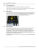
1.3 VisualDepth for Visual Plus 3 A Few Suggestions Before you begin to use your VisualDepth unit, please take a few minutes to: · Write down the VisualDepth serial number (located on the bottom of the main module) on your sales receipt. File your sales receipt for future reference. 1.4 Main Module The VisualDepth main module contains electronics to measure movement of gauge wires in probes and to route video signal from the appropriate front port to the video capture device.
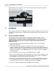
Introduction 1.6 7 Internal Probe The VisualDepth internal probe contains a spring loaded gauge wire coupled to a linear encoder, a video camera, a light source, and a probe positioning system. The VisualDepth main module measures travel of the gauge wire when it is pressed against a reference surface and compares it to travel when the gauge wire is inserted into a pit. The difference between two readings is displayed in VisualPlus software as pit depth.
VisualDepth for Visual Plus 3 bottom, sidewall or the crown the small end of the probe handle indicates the direction in which the gauge wire is pointing. 2 Installation Please follow instructions in the following sections to install VisualDepth on your system. It is very important to perform driver installation before plugging anything into USB ports on your computer. 2.
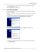
Installation 9 7. Once installation has been completed you will be taken to the 'Installation Complete' page. Click Close on this page. 8. The VisualPlus software is now installed. 2.2 Install USB Video Adapter The USB video adapter driver needs to be installed to provide video guidance and capture functions to VisualDepth. 1. Place the VisualPlus CD supplied with VisualDepth into the CD-ROM drive (if not already inserted). 2. Plug the USB Video adapter into a USB 2.0 port on your computer.
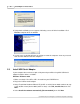
VisualDepth for Visual Plus 3 5. Verify that the following screen appears indicating successful driver installation. Click Finish to complete driver installation. 6. In some cases a window will come up asking to restart the computer. Save any unsaved work and click Yes to restart the computer. 2.3 Install USB Serial Adapter If your computer does not have a 9pin serial port and you will be using SIIG USB-Serial adapter install the drivers as follows: Windows XP/Server 2003 1.
Installation 11 5. Click Finish. 6. Repeat steps 3-5. 7. You may need to restart the computer to complete the installation. Vista 1. Plug in the USB to Serial adapter. 2. At the Found New Hardware Window, click Locate and install the driver software (recommended), then click Continue. 3. Click Close, then click Next. 4. Click Close and restart Windows to complete the installation. Verify Windows Installation 1. Check Device Manager to verify successful driver installation.
VisualDepth for Visual Plus 3 4. Connect the power supply (5v) to the Power In port on VisualDepth main unit. 2.4.2 Front Panel Connections Front panel connections are listed in the order they appear on the illustration below. The listing is from top down. 1. Connect external probe to External Probe port on VisualDepth main unit. 2. Connect internal probe to Internal Probe port on VisualDepth main unit. 3. The OpticalPlus Video port is for an optional video thread inspection accessory.
Installation 2.5 13 Configuring Software Visual Plus software connects to VisualDepth instrument via an RS232 link. In order to properly communicate with Visual Plus you must specify a COM port that the unit is connected to. Typically for laptops it will be COM1, if you use a USB-Serial adapter the COM port number is hard to predict. Unless you know the exact COM port number that VisualDepth is connected to please follow steps 1 through 7, otherwise please skip to step 8: 1. Go to Start->Control Panel.
VisualDepth for Visual Plus 3 3 Using VisualDepth 3.1 Calibrating VisualDepth should be periodically tested to make sure that it is reading correct depth values. Please refer to the following section for information on how to take measurement with internal and external probes. To verify proper operation of VisualDepth system repeat the following procedure with both the internal and external probes: 1. Set zero on the top surface of the Reference Gauge. 2. Measure the depth of pit marked 0.03" and 0.
Using VisualDepth 15 Please note that the reference gauge can be mounted to a fixed surface through a countersunk hole in the middle. 3.2 Measuring Pit Depth Pit depth measurement is part of visual inspection and it is integrated into the Visual Inspection form. To access measurement capabilities of VisualDepth start visual inspection form by pressing F3 or selecting Inspection->Fill Out Inspection Form from the main menu.
3.2.1 VisualDepth for Visual Plus 3 External Pits To measure external pits: 1. Place the external probe gauge wire on a good surface next to the pit and press on the probe so that both reference prongs are touching the surface of the cylinder. The probe should be perpendicular to the cylinder surface. Press the left foot switch or F4 to set zero while holding the probe in this position. The Depth value should change to 0.000in. 2.
Using VisualDepth 17 Measurements box into the Visual Inspection form. 3.2.2 Internal Pits Internal probe orientation should be set according to location of a pit to be measured. In addition, the movement of the probe needed to press reference prongs against cylinder surface will be different depending on the location. Please review the following sections to understand how to inspect different parts of the cylinder. 3.2.2.1 Inserting Internal Probe To insert the internal probe into a cylinder: 1.
VisualDepth for Visual Plus 3 up any slack in the positioning cable), the probe should be co-linear with the main shaft now. 4. Take up slack on the probe cable so that it is routed through a cutout in the probe swivel fork. Carefully insert the probe and the main shaft into the cylinder. This is normally a close but loose fit. You should not have to use ANY force to insert the probe. If you encounter resistance please remove the probe and contact the factory.
Using VisualDepth 3.2.2.2 19 Removing Internal Probe To remove the internal probe from a cylinder (please refer to illustrations in the previous section): 1. Loosen handle thumbscrew and rotate the handle wheel so that letter B is visible in the position indicator hole. 2. Rotate the handle wheel to position E (the movement to B and then to E is used to take up any slack in the positioning cable), the probe should be co-linear with the main shaft now. 3.
VisualDepth for Visual Plus 3 the end of the text. If the curvature of the cylinder is different at the new location then repeat from step 5. An easy way to check if the curvature is the same is to press the probe against the good cylinder surface as in step 5 and check that the depth is reading as 0.000in. 9. Once all pits have been measured press Enter to copy text from Recorded Measurements box into the Visual Inspection form.
Using VisualDepth 21 Inspecting the angled portion of the cylinder bottom Measurement procedure (cylinder sidewall): Use same procedure as in the beginning of this section with the following differences: 1. Set the probe handle wheel to letter S. 2. When taking a measurement the probe should be moved directly toward the sidewall. The best way to achieve this is to position the probe over the pit and then press on the main shaft where it enters the cylinder in the direction of the sidewall.
VisualDepth for Visual Plus 3 Inspecting cylinder sidewall Measurement procedure (cylinder crown): Use same procedure as in the beginning of this section with the following differences: 1. Set the probe handle wheel somewhere between letter S and letter M. The exact position depends on location of a pit. 2. When taking a measurement the probe should be moved up and towards the sidewall, depending on location of the pit.
Using VisualDepth 23 Inspecting cylinder crown Please note that the VisualDepth internal probe is not capable of measuring any pits that are too close to the threaded hole in the cylinder crown. Approximately 1 inch (25mm) circular area from where threads end cannot be measured. Please use traditional methods if you encounter a pit in this area.
VisualDepth for Visual Plus 3 Limitations on measurement in the cylinder crown. This view is from the inside of the cylinder. 3.3 Care & Maintenance VisualDepth probe is a sensitive electronic device and requires following care: 1. It is extremely important to prevent damage to the gauge wire on the end of either probe. If this wire is bent at a sharp angle, remove the two screws attaching probe head to the probe body. Remove probe head. Using small pliers carefully straighten the wire.
Using VisualDepth 25 those are not backing out, if they get backed out while in a cylinder the probe might be stuck. 4 Specifications System power supply Universal, Input: 110/220V, 50/60Hz, Output: 5V@2.5A Internal/External Probe Resolution .0014in (0.036mm) Internal/External Probe Accuracy +/- 0.003in (0.076mm) Internal/External Probe Measurement Range 0.15in (3.8mm) or greater Internal Probe Swivel Rotation Range 160 degrees Internal Probe Diameter (including swivel mechanism) 0.94in (23.