
User manual


VisualDepth for Visual Plus 36
(c) 2006-09, Saryna Technologies LLC/Advanced Inspection Technology
1.3 A Few Suggestions
Before you begin to use your VisualDepth unit, please take a few minutes to:
· Write down the VisualDepth serial number (located on the bottom of the main module) on
your sales receipt. File your sales receipt for future reference.
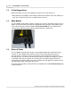
1.4 Main Module
The VisualDepth main module contains electronics to measure movement of gauge wires in
probes and to route video signal from the appropriate front port to the video capture device.
To turn the unit on press the push button below Power On/Off label. A red light should
come on to the right of the push button to indicate that unit is powered on.
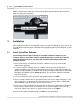
1.5 External Probe
The VisualDepth external probe contains a spring loaded gauge wire coupled to a linear
encoder. The VisualDepth main module measures travel of the gauge wire when it is
pressed against a reference surface and compares it to travel when the gauge wire is
inserted into a pit. The difference between two readings is displayed in VisualPlus software
as pit depth. Two reference prongs are used to make sure that the gauge wire travel is
measured from a known location. The probe should be pushed against the cylinder surface
until both prongs make contact with the surface.
The probe cable should be connected to the VisualDepth main module External Probe port
on the front panel.